

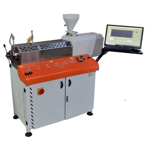
AHP FPV test system with PC-based acquisition and reporting.
| Document | Operator Manual |
| Equipment | Filter Pressure Value (FPV) Tester |
| Manufacturer | AHP PLASTIK MAKINA |
| Edition | 2023 |
1. Purpose and Scope
This manual provides the operating sequence demonstrated for the AHP Filter Pressure Value Tester: installation checks, cooling-water connection, temperature and pressure safety settings, manual operation, purging, screen-pack installation, PC-controlled testing, interpretation of the pressure graph, FPV calculation, reporting, shutdown and routine operator care. It is written so that a trained laboratory operator can reproduce the demonstrated workflow without relying on the video during normal operation. It also includes an operator-oriented implementation of EN 13900-5:2005 for the standard FPV determination.
2. Safety Information
- Hot surfaces: barrel, die/head, melt pump, breaker-plate area and discharged polymer may be at approximately 170–230 °C or higher depending on the method. Wear heat-resistant gloves and eye/face protection.
- Pressure hazard: molten polymer is pressurized. Never loosen the head nut, breaker-plate holder, screen pack or process fittings while melt pressure is present.
- Rotating machinery: keep hands, tools and loose clothing away from the hopper throat, screw drive and moving drive components.
- Cooling water: confirm inlet/outlet hoses are secure before heating. The demonstrated water circuit cools the barrel sleeve directly below the hopper.
- Emergency stop: know the location of the red emergency-stop button before operating. Do not bypass pressure, temperature or cold-start interlocks.
- Purging: hot polymer exits the head. Keep a heat-resistant collection container and tools ready; maintain a clear discharge zone.
- PC/manual mode: verify the selector position before commanding motion. Unexpected screw or pump motion can occur if the wrong mode is selected.
| CRITICAL: Do not remove or install the screen pack until the extruder is stopped and pressure is relieved. The training video specifically demonstrates stopping the main motor before installing the filter. |
3. System Overview
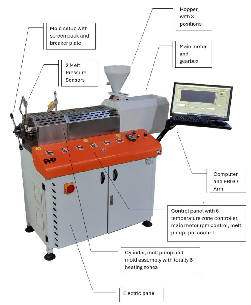
Figure 1 — Heated extrusion section and six-zone temperature-control panel.
| Subsystem | Function |
| Extruder / screw | Melts and conveys the polymer; screw speed is automatically adjusted in PC mode to maintain the selected pressure before the melt pump. |
| Melt pump | Provides controlled melt flow through the filter/screen pack. |
| Breaker plate / holder | Carries the selected screen pack and seals it in the head. |
| Pressure indication | Separate pressure measurement before and after the melt pump. |
| Six temperature zones | Independent temperature controllers for barrel / melt-pump heating / end heating zones. |
| PC software | Displays melt temperature and pressure trends, accepts test parameters, supports cursor selection and Word reporting. |
| Cooling-water sleeve | Located below the hopper; requires water inlet and outlet connection. |
4. Installation and Pre-Start Connections
- Install the laptop/computer support arm on the two provided mounting brackets.
- Place the supplied laptop on the arm. The software is pre-installed on the supplied computer.
- Connect cooling-water inlet and outlet hoses to the connections serving the cooling sleeve below the hopper.
- Check that the discharge/head area is clear and that the breaker-plate holder can be safely accessed.
- Connect electrical power according to the machine nameplate and site electrical requirements.
- Release the emergency stop and confirm that all displays power up.

Figure 2 — Cooling-water inlet/outlet connections on the rear/lower machine section.
5. Operator Controls and Interlocks
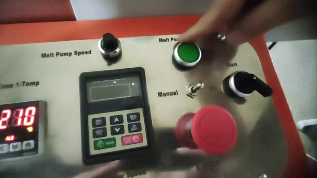
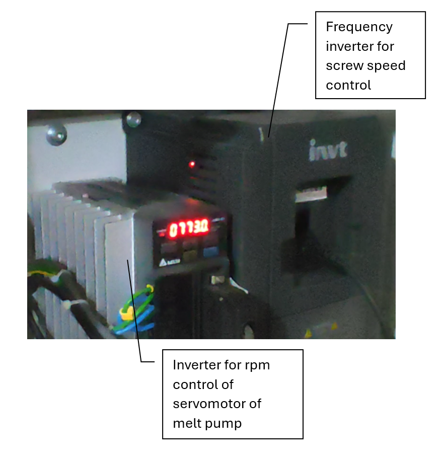
Figure 3 — Main operator controls: melt-pump speed control, manual melt-pump control, run control and emergency stop.
| Control / Display | Operator use |
| MANUAL / PC selector | MANUAL: local extruder operation. PC: computer-controlled test operation. |
| RUN control | Starts/stops the extruder when permitted by the selected mode and safety interlocks. |
| Melt Pump Speed potentiometer | Sets melt-pump servo speed; the demonstrated working range during testing is approximately 500–750 rpm. |
| Manual Melt Pump control | Used when required to run the melt-pump servo manually, including reducing pressure after the pump before releasing the cartridge/breaker-plate holder. |
| Emergency stop | Stops machine motion in an emergency. Reset only after the hazard has been removed. |
5.1 Pressure Safety Limits
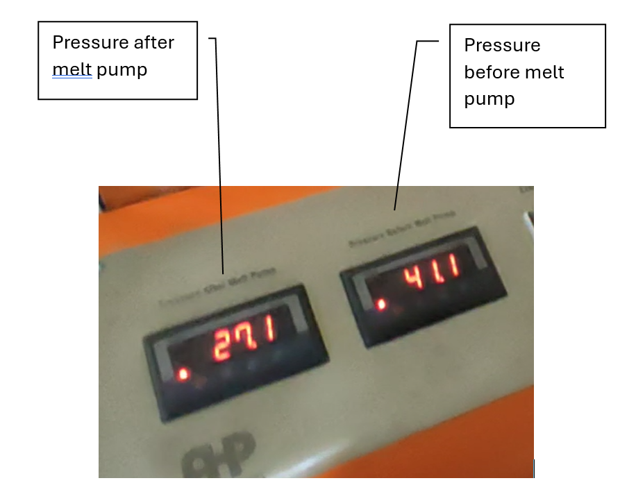
The machine has pressure indication before and after the melt pump. Each pressure indicator includes a safety relay. In the demonstrated setup, the before-pump high limit was shown as 30 bar and the after-pump high limit as 170 bar. If the applicable pressure exceeds its set limit, the associated drive is stopped for protection.
- On the pressure indicator, press MODE to display the limit setting (shown as “L Set” / “LS” in the video).
- Read the configured value.
- Change the value only if required by the approved method or authorized setup.
- After adjustment, verify the limit before starting material flow.
| IMPORTANT: The 30 bar and 170 bar values are demonstrated setup values, not universal limits for every material or method. Do not increase a safety limit merely to prevent nuisance trips. |
5.2 Temperature Zones and Cold-Start Protection
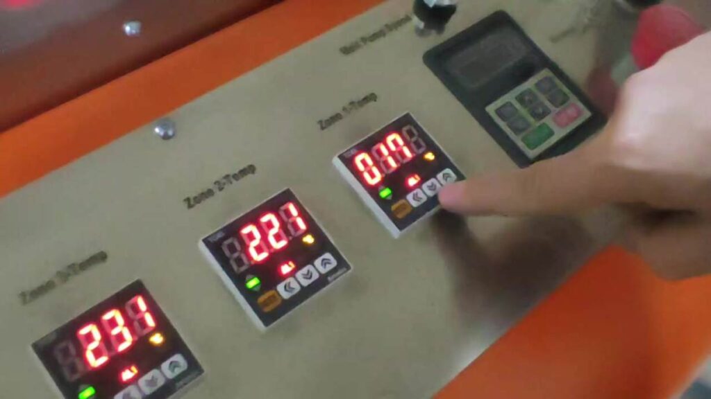
Figure 4 — Temperature controller setpoint adjustment on the front panel.
Six independent temperature controllers heat the cylinder/barrel and melt-pump/end zones. These controllers operate independently of the PC software.
- Select the required temperature controller.
- Use the arrow/digit keys to select and change the set value.
- Confirm/store the value using the MODE key as demonstrated on the controller.
- Repeat for all six zones according to the test method and material.
- To inspect the cold-start alarm threshold, press and hold MODE until the alarm parameter is displayed; the video demonstrates Alarm 1 = 170 °C.
- When all six zones have exceeded their alarm threshold, the digital soak timer starts. The demonstrated timer is set to 25 minutes.
- Only after all alarm contacts are active and the 25-minute soak has completed is the main motor permitted to run.
| COLD-START PROTECTION: Do not bypass the 170 °C alarm logic or the 25-minute soak timer. Its purpose is to prevent screw/melt-pump operation while polymer in the heated path is still too cold. |
6. Manual Start-Up and Purging
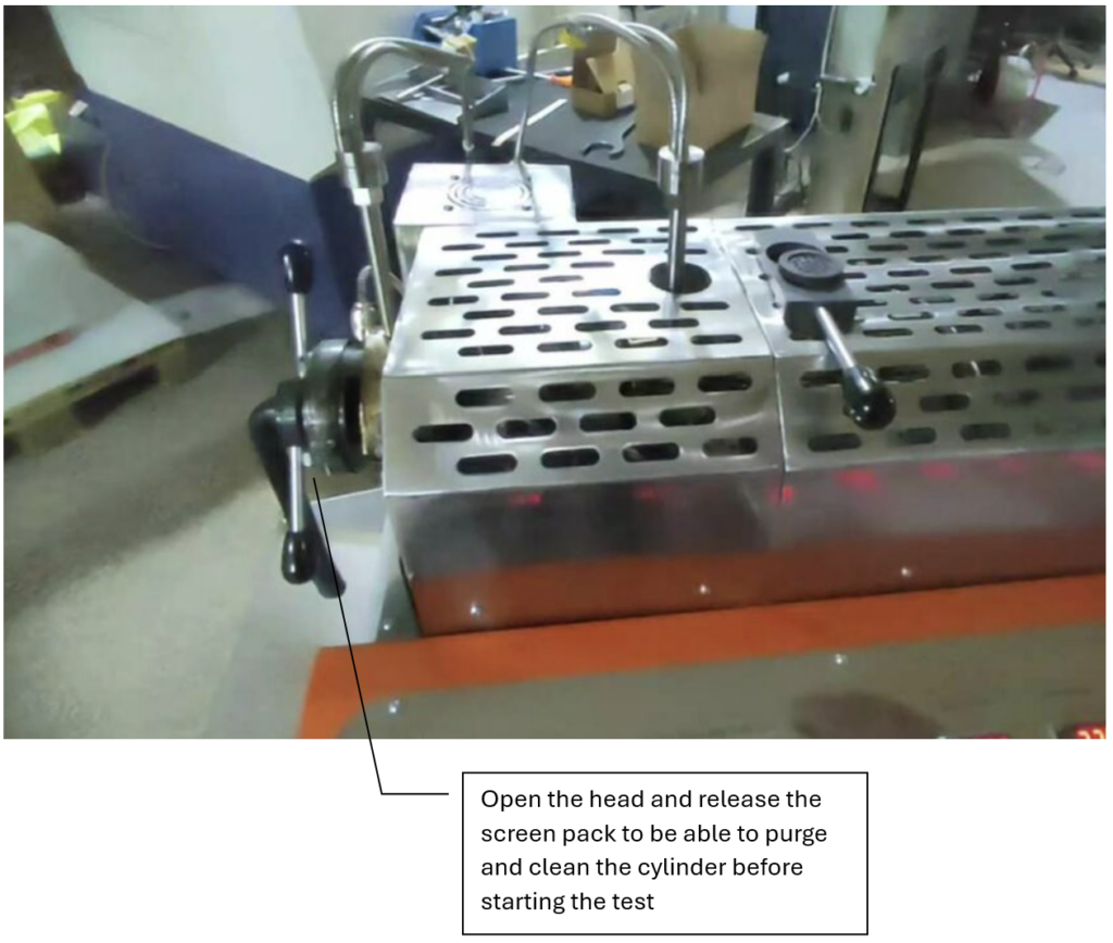
Figure 5 — Open head / discharge configuration used for purging before installing the screen pack.
- Before purging, remove the breaker-plate holder/screen pack so that the melt path is open.
- Secure/tighten the head hardware as demonstrated so the open discharge path is mechanically safe.
- Confirm all six zones are at temperature and the cold-start timer has completed.
- Set the mode selector to MANUAL.
- Start the extruder with the RUN control.
- Adjust screw speed with the local speed control as needed for purging.
- Add clean virgin polymer to the hopper.
- Continue extrusion until the material leaving the head is visibly clean and free from the previous black/colored material.
- Stop the extruder before installing the screen pack.
| WHY PURGING MATTERS: User manual emphasizes cleaning with virgin material after each test. Installing a fresh filter while contaminated material remains in the barrel causes continuing pressure build-up before the mesh and prevents a stable starting pressure. |
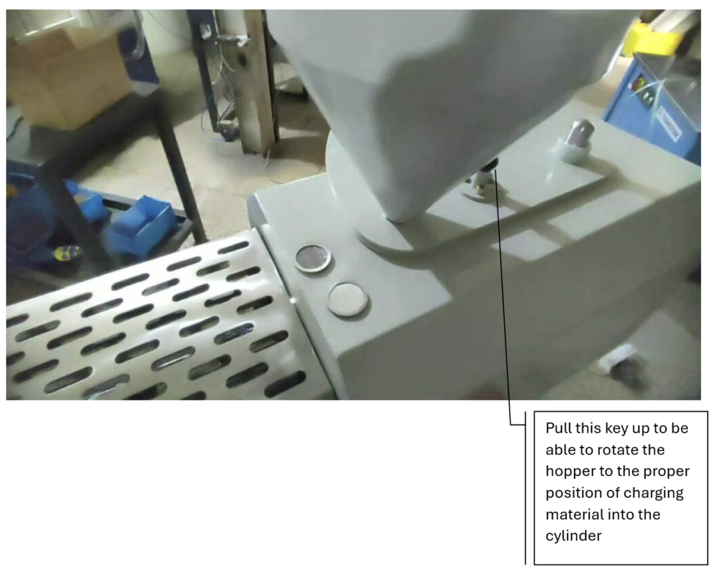
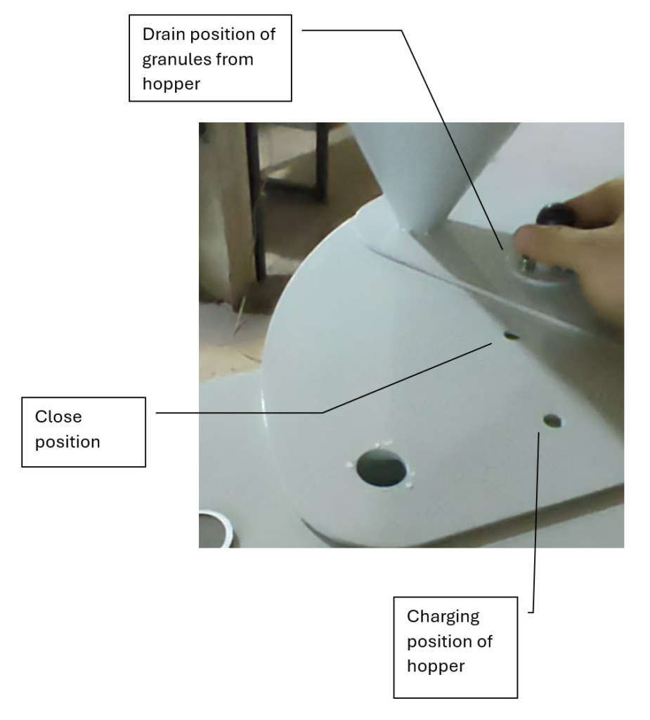
Figure 6 — Hopper throat and feed area used while purging with clean virgin granules.
7. Screen Pack / Breaker Plate Installation
The machine is supplied/used with different filter sizes. The demonstration uses a 10 µm screen pack consisting of a fine mesh, backup mesh and aluminum sealing ring assembly.
- Stop the main extruder motor.
- Verify that melt pressure has been relieved. If necessary, use the manual melt-pump control to reduce pressure after the pump.
- Select the required screen pack for the method (10 µm is demonstrated).
- Confirm the fine mesh, backup mesh and aluminum sealing ring are correctly assembled and undamaged.
- Place the screen pack into the breaker plate / holder.
- Use the wrench to open the head nut sufficiently to insert the holder.
- Insert the breaker-plate holder fully into the head.
- Tighten the head nut firmly. Tightening compresses the aluminum sealing ring around the mesh to create a sealed flow path.
- Inspect the assembly for correct seating before restarting.
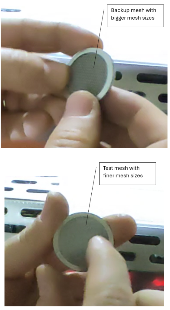
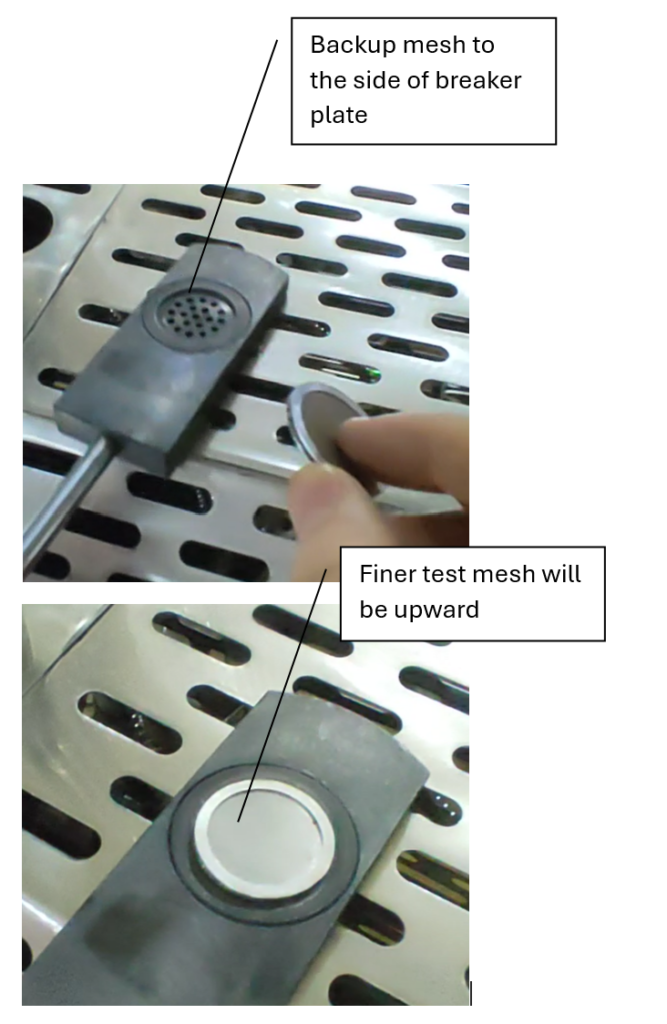
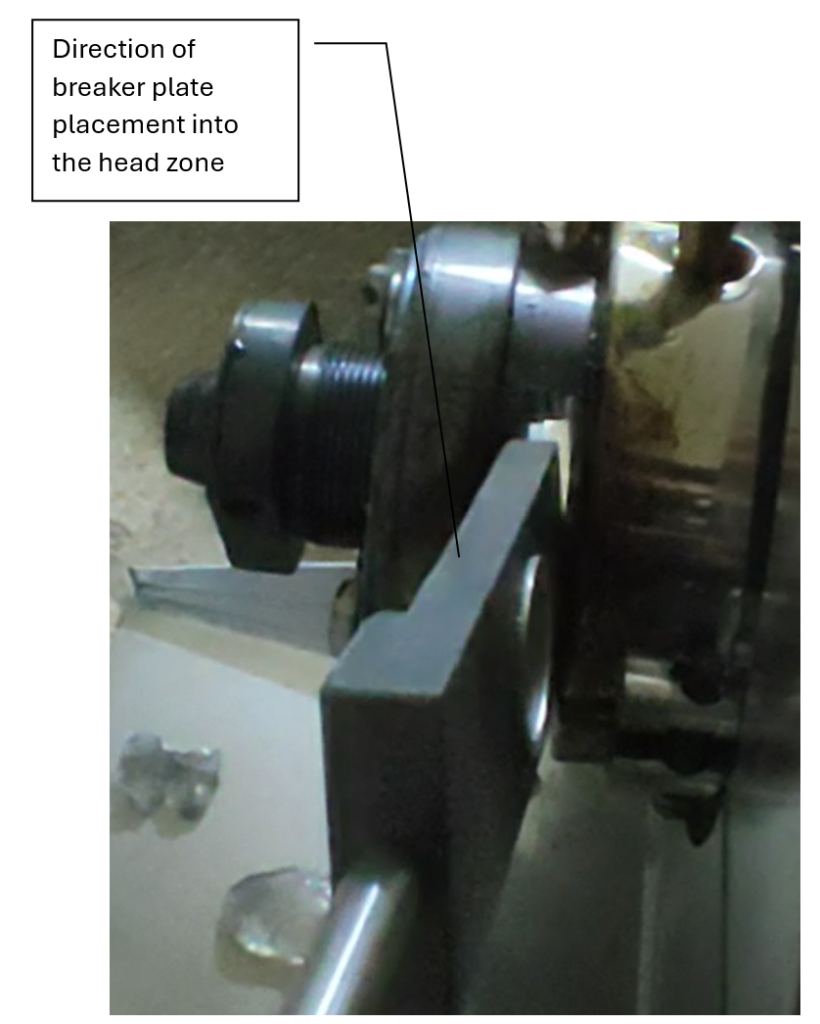
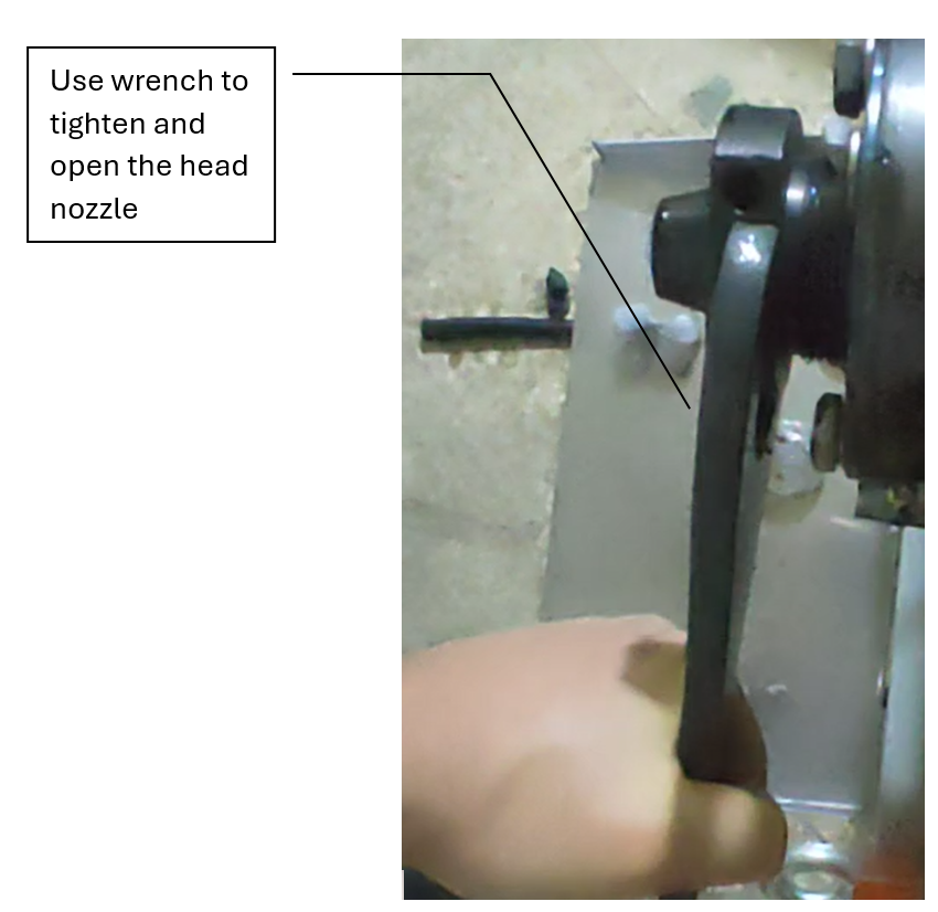
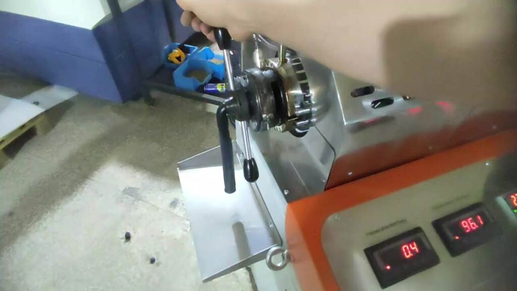
Figure 7 — Head nut and breaker-plate holder area during filter installation/removal.
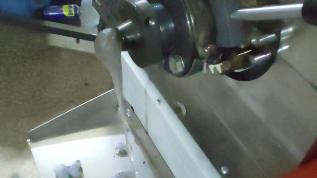
Figure 8 — Polymer discharge from the head during the operating sequence.
| PRESSURE RELEASE: Never use the wrench on the head nut while the melt path is pressurized. Stop motion and reduce pressure first. |
8. Standard Test Method — EN 13900-5:2005
This section converts the requirements of EN 13900-5:2005 into an operator sequence for the AHP Filter Pressure Value Tester. The FPV result is method-dependent: results are comparable only when the same equipment configuration, test polymer, mixture preparation, screen pack and test conditions are used.
8.1 Principle of the Standard Method
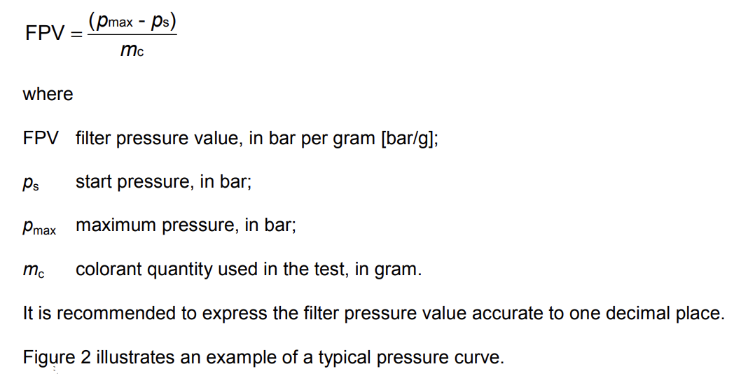
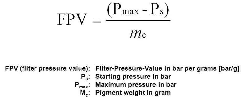
A homogeneous test mixture consisting of colour concentrate and a basic thermoplastic test polymer is plasticized in a single-screw extruder, metered by a melt pump and forced through a defined screen pack supported by a breaker plate. Melt pressure is measured immediately upstream of the filter. The increase from the stable start pressure (Ps) to the maximum pressure (Pmax) is divided by the actual mass of colorant (Mc) used in the test.
8.2 Standard Apparatus Conditions
| Item | EN 13900-5 requirement / recommendation | Operator relevance |
| Extruder | Single screw; non-grooved barrel; screw without dispersing elements. Recommended screw diameter 19–30 mm and 20–30 L/D. | Use the approved AHP machine configuration; do not change screw geometry when comparing FPV results. |
| Pressure before melt pump | Closed-loop screw-speed/pressure control; preferably 30–60 bar. | Enter the before-pump pressure setpoint in the PC software and wait for stable control. |
| Melt pump | Constant melt volume throughput of 50–60 cm³/min. | Use the validated pump setting that produces the required throughput; RPM alone is not the standard quantity. |
| Filter pressure transducer | Preferred range 0–100 bar for Mixture 1 and 0–350 bar for Mixture 2; accuracy within ±1%; repeatability < ±0.1%; 0.1 bar resolution recommended. | Confirm the installed transducer range/calibration is suitable for the selected mixture. |
| Melt temperature | Stable during determination; deviation less than ±2 °C. | Do not begin evaluation until thermal conditions are stable. |
| Screen pack / sealing | Defined screen pack, correctly oriented and edge-sealed; filter disc Ø33.8 ±0.1 mm; sealing/frame ID 28 ±0.1 mm. | Install a new screen pack for each determination and prevent bypass around its edge. |
8.3 Screen-Pack Selection
The standard defines three screen-pack constructions. Their weave, wire diameter, aperture and layer order are critical because any change can change the FPV result. Use only screen packs whose specification is traceable to the selected test method. The melt must pass through the finer screen first and through the breaker plate last.
| Screen pack | Construction specified by EN 13900-5 |
| 1 | 2 layers: reverse plain Dutch weave 615/108 per 25.4 mm, wire Ø0.042/0.14 mm; support mesh plain weave, 0.63 mm aperture, wire Ø0.40 mm, calendered. |
| 2 | 2 layers: reverse plain Dutch weave 615/132 per 25.4 mm, wire Ø0.042/0.13 mm; support mesh plain weave, 0.63 mm aperture, wire Ø0.40 mm, calendered. |
| 3 | 3 layers: twilled Dutch weave 165/1400 per 25.4 mm, wire Ø0.071/0.040 mm; support mesh 0.25 mm aperture / Ø0.16 mm wire; second support mesh 0.63 mm aperture / Ø0.40 mm wire, calendered. |
8.4 Preparation of Standard Test Mixtures
Mix the colour concentrate and basic test polymer thoroughly in a clean glass or plastics container to obtain a homogeneous mixture. Mixture 1 is recommended for colour pigments; Mixture 2 is recommended for white and carbon-black pigments. Colorant quantities below 5.0 g are not suitable for adequate accuracy.
| Mixture | Total mixture | Actual colorant | Example for 40% colorant masterbatch | Typical use |
| Mixture 1 | 200 g | 5.0 g (2.5%) | 12.5 g concentrate + 187.5 g basic polymer | Colour pigments |
| Mixture 2 | 1000 g | 80.0 g (8%) | 200 g concentrate + 800 g basic polymer | White / carbon black pigments |
8.5 Standard Determination — Step-by-Step
1. Pre-heat the complete apparatus to the processing temperature appropriate for the selected basic test polymer.
2. Clean/purge the complete melt path thoroughly with the basic test polymer before every test.
3. Stop the machine, relieve pressure and install a NEW specified screen pack in front of the breaker plate. Orient it so the melt meets the finer screen first. Confirm the sealing ring/frame prevents edge bypass.
4. Allow sufficient time for the newly installed screen pack and breaker plate to reach the machine operating temperature.
5. Start feeding the basic test polymer. Operate the melt pump at the validated constant throughput of 50–60 cm³/min and maintain the before-pump melt pressure preferably between 30 and 60 bar using the automatic screw-speed/pressure loop.
6. Wait until melt temperature and pressure are stable. During the determination, melt-temperature deviation shall remain below ±2 °C.
7. Observe the pressure immediately upstream of the screen pack. Establish and record a stable start pressure Ps using only the basic test polymer.
8. Allow the hopper level to fall. When the hopper is empty and the extruder screw is just visible, add the complete prepared test mixture.
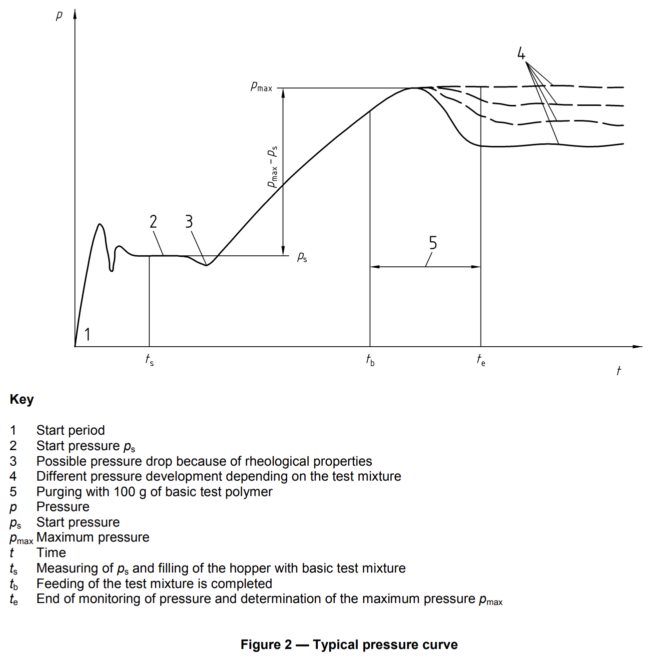
9. Continue recording pressure continuously. A temporary pressure drop after changing from basic polymer to test mixture can occur because of rheological differences and is not, by itself, the maximum-pressure result.
10. After the test mixture has been completely fed, wait until the screw becomes visible again, then add exactly 100 g of the basic test polymer.
11. Continue monitoring the filter pressure while this 100 g purge portion passes through the system.
12. The determination ends when the extruder screw becomes visible again. From the recorded pressure curve determine the maximum pressure Pmax.
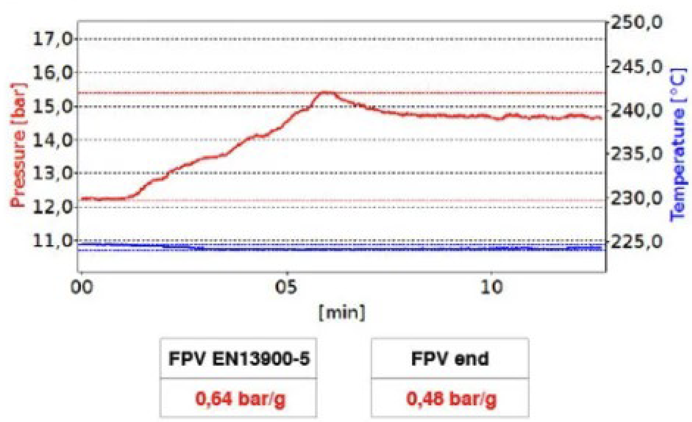
13. Calculate FPV = (Pmax − Ps) / Mc, where Mc is the actual mass of colorant in grams. Report FPV in bar/g, preferably to one decimal place.
14. While the head is still hot and after pressure has been safely relieved, remove the used screen pack and thoroughly purge the apparatus with basic test polymer before the next determination.
IMPORTANT — Difference from the training demonstration
The training video demonstrates the machine controls and the principal FPV sequence. For a test claimed to follow EN 13900-5:2005, the operator shall additionally follow the standard-specific requirements above, especially: defined 50–60 cm³/min melt throughput, melt-temperature stability within ±2 °C, a new correctly oriented specified screen pack, and addition of 100 g basic test polymer after the test mixture before determining the end of monitoring.
8.6 Evaluation of the Pressure Curve
Use the software pressure-after-pump/filter graph to identify Ps on the stable baseline and Pmax as the highest valid pressure reached during the defined monitoring period. Do not select a short electrical/noise spike. The software cursor positions shall correspond to the recorded physical pressure curve.
FPV [bar/g] = (Pmax [bar] − Ps [bar]) / Mc [g]
8.7 Minimum Test Report Content
The test report shall identify: EN 13900-5; the colour concentrate; the basic test polymer; the test-mixture composition; test equipment and conditions (including screen-pack type, melt temperature and melt volume throughput); FPV result; any deviation from the method; and test date.
8.8 Standard Text
4 Principle
The test mixture, consisting of a color concentrate and a basic test polymer, is passed through an extruder fitted with melt pump and screen pack with breaker plate. In front of the screen pack is a melt pressure transducer. The pressure difference between the start pressure and the maximum pressure is used to calculate the filter pressure value [FPV].
6 Apparatus
6.1 General
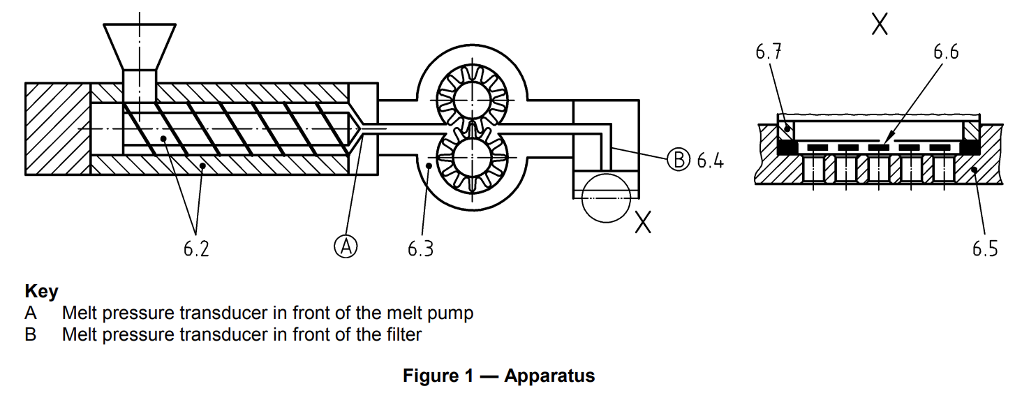
Figure 1 illustrates the principle construction of the apparatus (see 6.2 to 6.7).
6.2 Extruder
A single screw extruder with non-grooved barrel and a screw without dispersing elements shall be used. A screw with a diameter between 19 mm and 30 mm and with a length of 20 L/D to 30 L/D (length/diameter) is recommended. It is necessary to have a melt pressure transducer in front of the melt pump (A) to measure the pressure of the melt. An electronic controller with screw speed/pressure feedback loop is necessary in order to maintain this pressure constant, preferably at a level between 30 bar and 60 bar, to ensure that the melt pump is completely filled and to ensure optimum homogeneity of the melt.
6.3 Melt pump
The melt pump, preferably a metering pump, shall provide a constant throughput of 50 cm³/min to 60 cm³/min.
6.4 Melt pressure transducer
The pressure range shall be preferably between 0 bar and 100 bar for mixture 1 (7.2) and between 0 bar and 350 bar for mixture 2 (7.3). The accuracy of the melt pressure transducer (B) shall be within ± 1% with a repeatability of less than ± 0,1%.
NOTE The resolution of the pressure measurement should be 0,1 bar.
6.5 Breaker plate
A breaker plate is used to support the screen-pack and defines its free area (see Annex A).
6.6 Filter
6.6.1 General
The filter media is that part of the system which influences the differential pressure used as the basic data for determining the results of the test.
The differential pressure increase is dependent on the retention characteristics of the filter media.
In order to have comparable results it is important that the filter media is defined in detail and assembled exactly to specification.
Screen-packs are used as filter media. The screen-pack is assembled from ultrasonically cleaned filter discs, having a filter diameter of 33,8 mm (± 0,1 mm), in a multi-layer construction, preferably held together in an aluminium frame. All screens shall be made from a suitable material appropriate to the polymer used, e.g. stainless steel in accordance with EN 10088-1, Type 1.4404. Any change in specification (e. g. weaving pattern, surface condition, number of apertures per unit length or aperture width) can lead to a different test result.
6.6.2 Screen-pack 1
Two-layer construction, where the first layer is a reverse plain dutch weave 615/108 warp/weft per 25,4 mm with a wire diameter of 0,042 mm/0,14 mm and the second layer (support mesh) is a square mesh plain weave 0,63 mm aperture width with a wire diameter of 0,40 mm calendered (for further details see ISO 9044).
6.6.3 Screen-pack 2
Two-layer construction, where the first layer is a reverse plain dutch weave 615/132 warp/weft per 25,4 mm with a wire diameter of 0,042 mm/0,13 mm and the second layer (support mesh) is a square mesh plain weave 0,63 mm aperture width with a wire diameter of 0,40 mm calendered (for further details see ISO 9044).
6.6.4 Screen-pack 3
Three-layer construction, where the first layer is a twilled dutch weave 165/1400 warp/weft per 25,4 mm with a wire diameter of 0,071 mm/0,040 mm and the second layer (support mesh) is a square mesh plain weave 0,25 mm aperture width with a wire diameter of 0,16 mm and the third layer (support mesh) is a square mesh plain weave 0,63 mm aperture width with a wire diameter of 0,40 mm calendered (for further details see ISO 9044).
NOTE 1 The use of further finer screen-packs than described in 6.6.2 may be agreed between the interested parties.
NOTE 2 It is recommended to request confirmation from the supplier that the above specifications are used for the screenpack. Especially the number of apertures per unit length and the wire diameters of the individual layers are extremely critical for the result of the filter pressure value test.
6.7 Sealing ring
The sealing ring or aluminium frame of the filter disc should have a diameter of 33,8 mm ± 0,1 mm and an inside diameter of 28 mm ± 0,1 mm.
If the screen-pack has no aluminium frame a sealing ring is to be used.
7 Preparation of test mixtures
7.1 General
The colour concentrate (5.1) and the basic test polymer (5.2) are mixed together, for example in a glass or plastics container, to provide the homogeneous test mixture.
NOTE 1 Mixture 1 is recommended for colour pigments and mixture 2 is recommended for white and carbon black pigments.
NOTE 2 The use of other mixtures may be agreed between the interested parties.
NOTE 3 Colorant quantities below 5,0 g will lead to insufficient accuracy.
7.2 Mixture 1
A test mixture of 200 g (100 %), including 5,0 g colorant (2,5 %) is used.
NOTE If the colour concentrate contains 40% colorant the quantities are: 12,5 g colour concentrate and 187,5 g basic test polymer.
7.3 Mixture 2
A test mixture of 1000 g (100 %), including 80,0 g colorant (8 %) is used.
NOTE If the colour concentrate contains 40% colorant the quantities are: 200 g colour concentrate and 800 g basic test polymer.
8 Procedure
8.1 Pre-conditioning
The complete apparatus (Clause 6) should be pre-heated to the processing temperature appropriate for the basic test polymer.
The equipment should be cleaned or adequately purged with the basic test polymer (5.2) before each test is started.
8.2 Determination
Mount a new screen-pack (6.6.2 to 6.6.4) in front of the breaker plate (6.5) and the measuring equipment in such a way that the melt flows through the finer screen first and through the breaker plate last. A sealing ring (6.7) shall prevent leakage of the mixture around the edge of the screen-pack.
Allow sufficient time for the screen-pack and the breaker plate to reach the temperature of the equipment. This time will depend on the equipment being used. The basic test polymer (5.2) is then plasticized in the extruder and passed through the screen-pack with a defined melt volume throughput until the melt temperature and pressure remain constant. The machine conditions should guarantee a constant melt temperature, with temperature deviations of less than ± 2°C.
Measure the start pressure ps developed by the basic test polymer directly in front of the screen-pack. The start pressure ps should be constant. When the hopper is empty and the extruder screw is just visible, add the test mixture (5.3).
NOTE A pressure drop can occur because of different rheological properties of basic test polymer and test mixture.
After feeding of the test mixture is completed, 100 g basic test polymer are added just as the extruder screw becomes visible again.
The test is finished as soon as the extruder screw once again becomes visible. Use the recorded data to evaluate the maximum pressure pmax and to calculate the filter pressure value.
Remove the screen-pack while still hot and purge the apparatus thoroughly with basic test polymer for the next test.
9 Evaluation
The filter pressure value [FPV], defined as the increase of pressure per gram colorant, is calculated by using the following equation:
10 Test report
The test report shall contain at least the following information:
a) reference to this European Standard (EN 13900-5);
b) all necessary details to identify the color concentrate tested;
c) all necessary details to identify the basic test polymer;
d) description of the test mixture (Clause 7);
e) all necessary details about the test procedure and the test conditions (e. g. test equipment, type of screen pack, melt temperature, melt volume throughput);
f) result of the test, as indicated in Clause 9;
g) any deviation from the test method specified;
h) date of the test.
Filter Pressure Value (FPV) Testing and its Role in Masterbatch Manufacturing
Masterbatches can be described as essential components in the vibrant world of plastics manufacturing, that serve as concentrated formulations (pigment and/or additive concentrates) and perform the crucial function of imparting color, enhancing properties, and introducing functionalities to a wide array of plastic products. These formulations, comprising pigments, additives, or other modifiers, are pivotal in transforming raw polymers into a diverse range of end-use plastics. The meticulous control of masterbatch quality is paramount in ensuring the consistent and desired characteristics of the final plastic products. One crucial aspect of quality control in masterbatch production involves Filter Pressure Value (FPV) testing—an important process that scrutinizes the manufacturing process’s stability, integrity, and efficiency. In this context, understanding the role of filter pressure testing is fundamental to guarantee the reliability and performance of masterbatches throughout the intricate journey from production to the end product.
EN 13900-5 standard specifies the required equipment, including the extruder, melt pump, sieves, and breaker plate along with delineating the composition of the mixture, the testing protocol, and the evaluation criteria. FPV is introduced to gauge the quality and dispersion of pigments. Through standardized quality control measures, improvements in product quality become achievable. Furthermore, comparing FPV results facilitates the ranking of similar products from different vendors. Employing the FPV test for raw material assessments ensures product quality, while also enhancing the predictability of screen changer uptime. In terms of application and operation, it is suited for testing colorants presented as color concentrates in all polymers utilized for extrusion in melt-spinning processes. The testing mixture undergoes processing in a single screw extruder featuring a non-grooved barrel and a compression screw without additional mixing elements. The polymer melt is consistently delivered with a pressure range of 30 to 60 bar (435 to 870 psi) to the melt pump, maintaining a volume of 50 to 60 cm³/min (setting 660 on the Melt pump). As the polymer passes through the filter package, particles and agglomerates above a specific size are retained, causing a pressure increase that correlates with the colorant’s quality. The pressure difference between the initial and peak pressures is then employed in calculating the FPV, providing a comprehensive measure of filter performance.
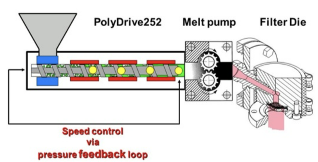
The polymer melt is ensured to flow through the finer screen first to prepare for the test. An aluminum rim of the screen pack serves as a seal to prevent undermining. Next, the breaker plate and screen pack are heated and the machine is purged with basic test polymer to expedite temperature equalization while maintaining a stable melt temperature within ±2°C. The basic test polymer is plasticized in the extruder, pumping it through the screen pack until melt temperature and pressure stabilizes. The melt pump feeding pressure should be 30 to 60 bar (435 to 870 psi), with a volume flow of 50 to 60 cm³/min. The equipment must be maintained at a constant melt temperature with deviations less than ±2°C. The pressure (Ps) developed by the basic test polymer just in front of the screen pack is measured for a constant value. When the hopper is empty, and the feed-screw is visible, the test mixture is introduced. A pressure drop due to differing rheological properties can be expected. With the hopper empty and the feed screw visible, refilling is done with the basic test polymer. The test is concluded after 100 g of basic test polymer passes through the screen pack and pressure stabilizes.
9. PC-Controlled Test Procedure
- Move the selector from MANUAL to PC.
- Enable/run the machine in PC mode.
- Enter the required pressure setpoint before the melt pump. The video states a selectable working setpoint of approximately 30–60 bar and demonstrates 30–40 bar.
- Enter the sample/test parameters in the software.
- Open the graph tabs and confirm that melt temperature, pressure after pump and pressure before pump are being acquired.
- Set melt-pump speed. The demonstrated test range is approximately 500–750 rpm.
- Start the test.
- Allow the control system to adjust screw rotational speed automatically until the pressure before the melt pump is maintained at the selected setpoint.
- Feed virgin/base polymer until a stable baseline pressure after the melt pump is obtained.
- Do not add the test mixture until the baseline after-pump pressure is essentially horizontal/stable and the hopper has emptied enough that the screw can be seen from the top.
- Add the prepared base-polymer/colorant mixture.
- Observe the discharge. When colored material reaches the head, the pressure after the melt pump begins to rise.
- Continue the run until the maximum pressure response is obtained and the mixture has passed through the system.
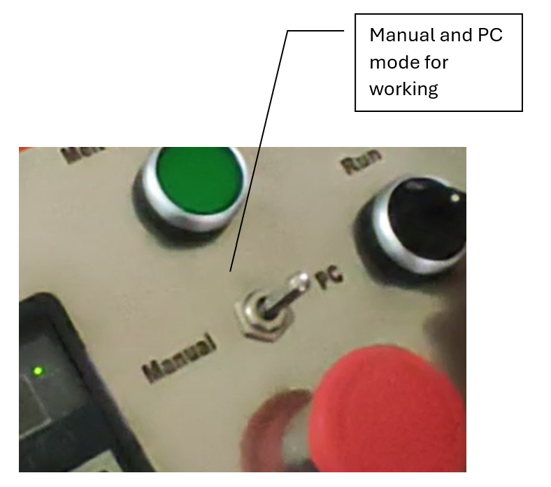
Figure 9 — Local control used while transitioning to the controlled test sequence.
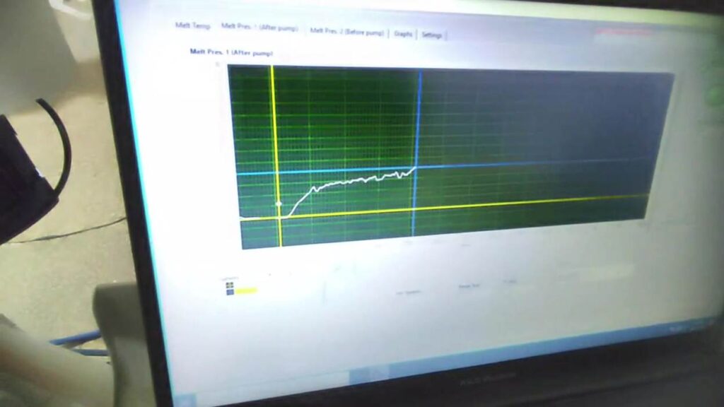
Figure 10 — PC pressure graph used to identify the stable starting pressure and maximum pressure.
9A. Software Interface and Operator Controls
This section explains the five principal software pages supplied with the AHP FPV system. The operator should use these pages together with the machine-panel instructions and the EN 13900-5 test procedure. Labels below follow the software exactly as shown. Where a field is application-specific rather than part of the FPV calculation, its purpose is described only to the extent visible in the supplied interface.
9A.1 Melt Temp Page
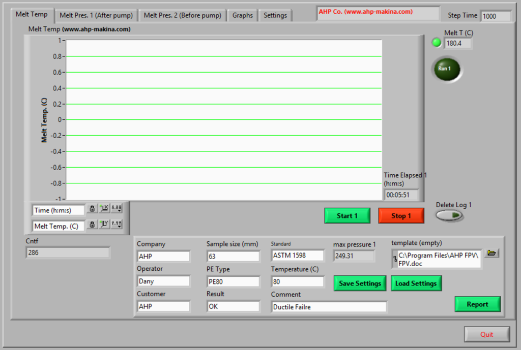
Figure 9A-1 — Melt Temp page: live melt-temperature acquisition, test information and reporting controls.
| Control / Field | Operator function |
| Melt T (C) | Live numerical melt-temperature reading. |
| Run 1 | Status indicator associated with temperature acquisition/logging. |
| Start 1 / Stop 1 | Starts or stops the temperature data log displayed on this page. |
| Time Elapsed 1 | Elapsed time of the active/recorded temperature log. |
| Delete Log 1 | Clears the stored/displayed temperature log. Use only when the current log is no longer required. |
| Company / Operator / Customer | Identification fields transferred to the test record/report. |
| Sample size / PE Type / Standard / Temperature / Result / Comment | Test-information fields used for documentation. Enter values applicable to the actual FPV test; do not rely on example values visible in the screenshot. |
| Save Settings / Load Settings | Stores or recalls the entered software/test-information settings. |
| Template | Path to the Microsoft Word report template used by the reporting function. |
| Report | Generates the test report using the configured Word template and available recorded data. |
| Quit | Closes the application. Stop the test and save required data before using this command. |
Operator note: The temperature graph is a monitoring record. EN 13900-5 requires the melt temperature to remain constant during the determination, with deviations less than ±2 °C. Confirm temperature stability before evaluating the pressure test.
9A.2 Melt Pres. 1 (After pump) Page — FPV Evaluation
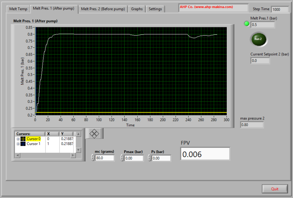
Figure 9A-2 — Pressure after melt pump / in front of the filter: primary FPV evaluation page.
| Control / Field | Operator function |
| Melt Pres. 1 (bar) | Live pressure reading for the pressure channel after the melt pump, i.e. the channel used to observe pressure development at the filter side in the demonstrated system. |
| Run 2 | Status indicator for pressure-channel logging. |
| Current Setpoint 2 (bar) | Displays the active setpoint associated with this channel/control function. |
| max pressure 2 | Maximum pressure detected/retained by the software for this pressure record. |
| Graph | Recorded pressure-versus-time curve. Establish a stable baseline before feeding the test mixture and continue recording through the pressure maximum. |
| Cursor 0 / Cursor 1 | Movable graph cursors used to identify the stable start pressure Ps and the maximum pressure Pmax. |
| mc (grams) | Actual mass of colorant in the test mixture, in grams. This is NOT automatically the mass of masterbatch. Example: 200 g of a 40% masterbatch contains mc = 80 g colorant. |
| Pmax (bar) | Maximum valid pressure selected from the recorded curve. |
| Ps (bar) | Stable start pressure obtained with the basic test polymer before the test mixture is introduced. |
| FPV | Calculated Filter Pressure Value: FPV = (Pmax − Ps) / mc, in bar/g. |
| Quit | Closes the software; save/report required test data first. |
CRITICAL: Select Ps from the stable baseline immediately before addition of the test mixture. Select Pmax as the highest valid pressure reached during the defined test monitoring period. Do not use an isolated electrical/noise spike as Pmax.
9A.3 Melt Pres. 2 (Before pump) Page — Extruder Pressure Control
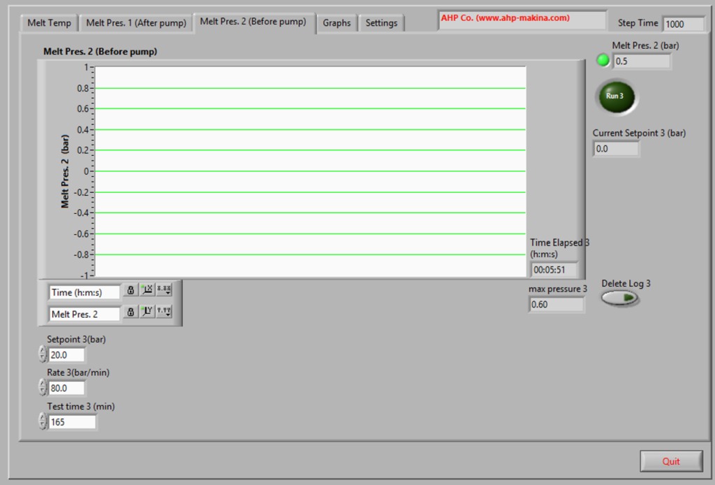
Figure 9A-3 — Pressure before melt pump: setpoint, rate, test time and pressure monitoring.
| Control / Field | Operator function |
| Melt Pres. 2 (bar) | Live pressure before the melt pump / at the extruder outlet. |
| Run 3 | Status indicator for this pressure-control/logging channel. |
| Current Setpoint 3 (bar) | Current commanded pressure setpoint. |
| Setpoint 3 (bar) | Target pressure entered by the operator. For the EN 13900-5 method, the pressure before the melt pump is preferably maintained between 30 and 60 bar. |
| Rate 3 (bar/min) | Programmed rate used by the control routine to approach/change the pressure setpoint. Use the validated machine setting; it is not an EN 13900-5 reporting parameter by itself. |
| Test time 3 (min) | Software time parameter for this control/logging routine. It shall not be used to override the standard end-point defined by the test procedure. |
| Time Elapsed 3 | Elapsed time for this pressure log. |
| max pressure 3 | Maximum value recorded on the before-pump pressure channel. |
| Delete Log 3 | Clears this channel log after required data have been saved. |
| Graph tools / axis locks | Graph navigation and axis-display controls; use them only for viewing the recorded data and avoid altering the interpretation of the actual recorded pressure values. |
During PC-controlled operation the software varies extruder screw speed to maintain the selected before-pump pressure. Confirm that the pressure has stabilized before beginning the standard test sequence.
9A.4 Graphs Page
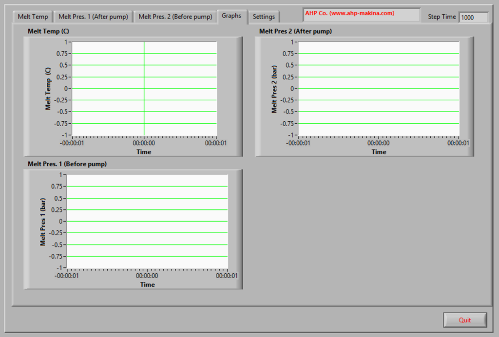
Figure 9A-4 — Combined graphs page for melt temperature and the two melt-pressure channels.
| Control / Field | Operator function |
| Melt Temp (C) | Overview plot of melt temperature versus time. |
| Melt Pres. 1 (Before pump) | Overview pressure plot for one pressure channel as labelled on this page. |
| Melt Pres 2 (After pump) | Overview pressure plot for the other pressure channel as labelled on this page. |
| Step Time | Display/acquisition step parameter shown by the application. The demonstrated value is 1000; change only if instructed for the installed software configuration. |
| Graphs tab | Use this page for simultaneous trend review. For FPV calculation, use the dedicated after-pump/filter pressure page where Ps, Pmax and mc are entered/selected. |
Label caution: The supplied software screenshots use “Melt Pres. 1/2” labels inconsistently between some tabs. For operation, identify the channels by physical function — BEFORE PUMP and AFTER PUMP / FILTER SIDE — and verify the live response during commissioning. The FPV curve must be taken from the transducer directly in front of the screen pack as required by EN 13900-5.
9A.5 Settings Page
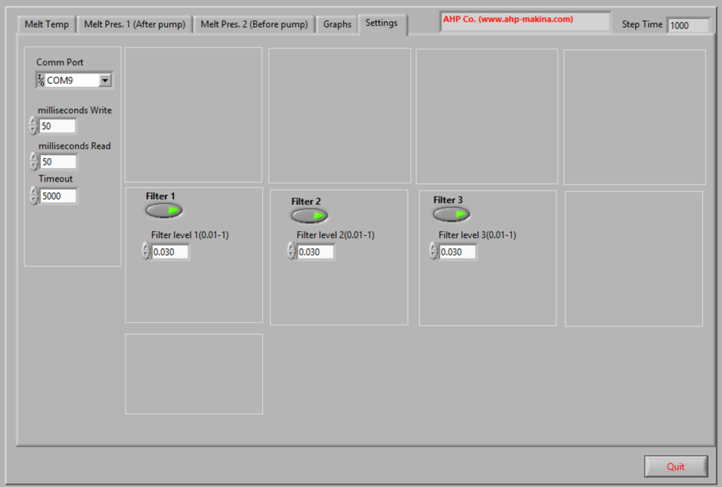
Figure 9A-5 — Settings page: communication timing and optional digital filtering.
| Control / Field | Operator function |
| Comm Port | Selects the serial communication port used by the machine interface (example shown: COM9). Select the port assigned to the connected AHP machine. |
| milliseconds Write | Communication write timing/delay parameter. Demonstrated value: 50 ms. |
| milliseconds Read | Communication read timing/delay parameter. Demonstrated value: 50 ms. |
| Timeout | Communication timeout parameter. Demonstrated value: 5000 ms. |
| Filter 1 / Filter 2 / Filter 3 | Enables/disables software filtering for the corresponding acquired channels. |
| Filter level 1 / 2 / 3 (0.01–1) | Filter coefficient/level for the corresponding channel. Demonstrated value: 0.030. Higher/lower values change response smoothing; do not alter validated values during a test series without documenting the change. |
| Step Time | Application acquisition/display step parameter; demonstrated value: 1000. |
| Quit | Closes the software. |
Recommended operator practice: Communication and filter settings are commissioning/service parameters. Once stable communication and validated signal response have been established, normal operators should not change them between comparable tests. Changing digital filtering can change the apparent shape and peak of the recorded pressure curve and therefore can influence the selected Pmax.
9A.6 Recommended Software Operating Sequence
1. Start the application and confirm the correct Comm Port. Verify that live melt temperature and both pressure channels respond normally.
2. Leave communication timing and filter parameters at the validated machine settings unless adjustment is required by authorized service personnel.
3. Enter the required test identification data and confirm the report template path.
4. On the BEFORE PUMP pressure page, enter the required pressure setpoint (preferably 30–60 bar for EN 13900-5) and allow the automatic screw-speed control to stabilize the pressure.
5. Confirm stable melt temperature and stable pressure with basic test polymer before introducing the test mixture.
6. Start/maintain logging of the AFTER PUMP / FILTER-SIDE pressure curve. When the hopper is empty and the screw becomes visible, feed the prepared test mixture as specified in the standard procedure.
7. Continue the standard sequence, including the 100 g basic test polymer purge after the test mixture when required by EN 13900-5, and monitor until the standard end point.
8. On the FPV evaluation page, place one cursor on the stable start pressure Ps and the other at the valid maximum pressure Pmax. Enter mc as the actual colorant mass in grams.
9. Verify the displayed FPV against FPV = (Pmax − Ps) / mc. Review the graph for abnormal spikes or an unstable baseline before accepting the result.
10. Complete sample/operator fields, generate the Word report, review all values, save the report, and only then clear logs or close the program.
10. Sample Mixture and Colorant Mass
For normative mixture preparation, use Section 8.4 of this manual. The video demonstrates Mixture 2 using a 1,000 g total mixture: 200 g masterbatch at 40% colorant plus 800 g basic polymer, giving Mc = 80 g actual colorant. Do not substitute masterbatch mass for actual colorant mass in the FPV calculation.
| Example | Base polymer | Masterbatch | Colorant fraction in masterbatch | Colorant mass Mc |
| 200 g total example | 187.5 g | 12.5 g | 40% | 5.0 g |
| 1,000 g demonstrated mixture | 800 g | 200 g | 40% | 80 g |
| METHOD CONTROL: Use the mixture composition and screen pack specified by the applicable test method/customer procedure. The examples above reproduce the training demonstration and are not a substitute for the controlled laboratory method. |
11. FPV Calculation and Graph Evaluation
The software calculates Filter Pressure Value from the rise in pressure after the melt pump relative to the stable starting pressure, normalized by the mass of colorant.
FPV = (Pmax − Ps) / Mc
| Symbol | Meaning |
| Pmax | Maximum pressure after the melt pump during the test. |
| Ps | Stable starting/base pressure after the melt pump before the test mixture reaches the filter. |
| Mc | Mass of colorant in the test mixture, in grams. |
| FPV | Filter Pressure Value calculated by the software from the selected pressures and colorant mass. |
- Place the yellow cursor on the stable baseline pressure Ps.
- Place the blue cursor on the maximum pressure point Pmax.
- Enter/confirm the colorant mass Mc. In the demonstrated 1 kg mixture, 200 g masterbatch × 40% colorant = 80 g colorant.
- Verify that the cursor positions correspond to the actual baseline and peak rather than transient noise.
- Read the calculated FPV value.
- Review the full graph before accepting the result.
12. Test Report
After the test is complete, use the REPORT command in the software. The demonstrated software exports the graph and test results to Microsoft Word. Before releasing the report, verify sample identification, test parameters, Ps, Pmax, Mc, FPV and the graph.
13. End-of-Test Cleaning and Shutdown
- Complete and save/export the test report.
- Stop the test and return the machine to a safe non-running state.
- Relieve melt pressure before opening the head.
- Remove the used screen pack using heat-resistant tools/PPE.
- With the head configured for safe open discharge, purge the barrel with clean virgin polymer.
- Continue purging until the exiting polymer is visibly clean. This is required after every test in the demonstrated procedure.
- Stop the extruder.
- If no further test is planned, follow the laboratory’s controlled heater cool-down and electrical shutdown procedure.
- Maintain cooling water as required during cool-down; disconnect only when safe for the equipment.
- Clean the work area and dispose of hot polymer/filter waste according to site procedure.
14. Routine Operator Inspection
| When | Check |
| Before each run | Cooling-water hoses secure; emergency stop functional; guards/head hardware secure; pressure and temperature displays active; PC communication available. |
| Before filter installation | Pressure relieved; correct screen pack; sealing ring intact; breaker plate clean. |
| During heating | All six zones rising normally; alarm thresholds reached; 25-minute soak completes. |
| During test | Before-pump pressure controlled at setpoint; after-pump baseline stable before mixture; no melt leakage around screen pack/head. |
| After each test | Purge with virgin polymer until clean; remove test residue; inspect filter/head area. |
15. Troubleshooting Guide
| Symptom | Likely check / operator action |
| Main motor will not run | Confirm all six temperature alarm contacts are active and the 25-minute cold-start timer has completed; check mode selector and emergency stop. |
| Pressure before pump does not reach setpoint | Confirm hopper contains material, PC mode is selected, test is running, and melt path is correctly assembled. |
| After-pump pressure is not stable before mixture | Continue virgin-material flow/purging; confirm old colored material has been removed and the screen pack was installed only after clean purge. |
| Pressure rises continuously before test mixture | Possible contamination/old material at the screen; stop safely, relieve pressure, remove filter and repeat the clean virgin purge. |
| High-pressure trip | Stop and investigate restriction, screen condition, material state and configured safety limit. Do not simply raise the limit. |
| Material leaks around screen pack/head | Stop, relieve pressure, inspect seating and aluminum sealing ring, then reinstall and tighten the head nut correctly. |
| No pressure after melt pump | Confirm melt-pump operation/speed and that material is present; check the graph/sensor response. |
| Graph available but FPV seems wrong | Recheck yellow baseline cursor, blue maximum cursor and entered colorant mass Mc. |
| Temperature zone does not heat | Stop test preparation; inspect controller indication and have qualified personnel check heater/sensor/electrical circuit. |
16. Operator Quick-Start Checklist
☐ Laptop arm installed / software available
☐ Cooling water connected below hopper
☐ All six temperature setpoints entered
☐ All six zones above alarm threshold
☐ 25-minute soak completed
☐ Pressure safety limits verified
☐ Head purged with clean virgin polymer
☐ Correct screen pack assembled and sealed
☐ Mode switched to PC
☐ Before-pump pressure setpoint entered
☐ Melt-pump speed set
☐ Stable after-pump baseline obtained
☐ Test mixture added only after baseline is stable
☐ Pmax and Ps cursors positioned
☐ Colorant mass Mc confirmed
☐ Word report generated
☐ Used filter removed only after pressure relief
☐ Machine purged clean after test
Appendix A — Demonstrated Setup Values
| Parameter | Value shown/stated in training | Use |
| Temperature cold-start alarm | 170 °C | All six zones must exceed alarm threshold before soak timer can enable operation. |
| Cold-start soak timer | 25 min | Starts after all six temperature alarm contacts are active. |
| Before-pump pressure safety limit | 30 bar shown | Demonstrated protection setting; verify authorized setup. |
| After-pump pressure safety limit | 170 bar shown | Demonstrated melt-pump protection setting; verify authorized setup. |
| PC pressure setpoint before pump | 30–60 bar stated; 30–40 bar demonstrated | Control target for screw-speed regulation. |
| Melt-pump speed | Approx. 500–750 rpm during test | Set with front-panel potentiometer/controller. |
| Example screen pack | 10 µm | Demonstrated filter size. |
| Example mixture | 800 g base + 200 g masterbatch | 1,000 g demonstrated mixture. |
| Example masterbatch colorant content | 40% | 200 g × 40% = 80 g Mc. |
Appendix B — Items Requiring Machine-Specific Documentation
- Electrical supply voltage/frequency/current and protective device rating.
- Required cooling-water pressure, flow rate, temperature and connection size.
- Exact heater-zone mapping and normal setpoints for each material.
- Pressure-sensor ranges and calibration procedure/interval.
- Melt-temperature sensor location and calibration procedure.
- Approved screen-pack constructions and dimensions.
- Head-nut tightening torque, if a controlled torque is required.
- Lubrication/gearbox/melt-pump maintenance intervals.
- Software version, data-file location, backup procedure and report template control.
- Emergency-stop verification and electrical maintenance procedure.
| OPERATOR QUALIFICATION: This manual supports trained laboratory operation. Service work inside electrical panels, drive systems, heaters, pressure sensors or the melt pump should be performed only by qualified personnel using the applicable component documentation. |
Installation, Utilities, Safety and Preventive Maintenance
This section supplements the operating procedure with installation, cooling-water, operator-safety and preventive-maintenance guidance for the AHP Filter Pressure Value Tester. The requirements below are adapted to this machine from established extrusion-equipment practice. Where a site condition conflicts with the machine nameplate, electrical drawing or AHP project documentation, the machine-specific AHP documentation takes precedence.
Installation Site and Environmental Conditions
Install the machine indoors on a rigid, level and vibration-resistant floor or laboratory foundation. The machine shall not rock or twist when the extruder, melt pump and laptop arm are operated. Leave sufficient free space around the machine for loading material, removing the breaker-plate holder, servicing heaters and sensors, opening the electrical cabinet, and safely handling hot purge material.
Choose a dry, clean and well-ventilated location. Protect the machine from rain, dripping water, direct water jets, excessive dust, corrosive vapours and strong external heat sources. Keep the operator aisle and the area in front of the extrusion head unobstructed. Do not position a normal working station directly in front of the extrusion outlet because hot polymer can be expelled during start-up or abnormal pressure events.
Provide adequate room ventilation for polymer fumes generated during heating, purging and testing. If the processed polymer or additive supplier requires local exhaust ventilation, install extraction above/near the extrusion outlet without obstructing access to the head.
Before energizing the machine, verify the supply voltage/frequency against the machine nameplate, protective earth continuity, correct protective device rating, and secure electrical connections. The electrical cabinet shall remain closed during normal operation and shall only be opened by qualified electrical personnel.
Cooling-Water Supply
The cooling connections shown in the operating video serve the feed/cylinder region below the hopper. Cooling must be connected before production operation and water flow must be verified before the extruder is run.
Use clean cooling water that does not form heavy scale, corrosion deposits or biological fouling. As a conservative laboratory target, use filtered treated water with total hardness not greater than approximately 5 °dH and pH approximately 7.5 to 8.0. Water should be free of visible suspended solids, algae and aggressive oxidizing gases/chemicals. If local water quality is uncertain, use a closed-loop chiller or treated recirculating-water circuit rather than untreated mains water.
Install a small inlet strainer/filter where suspended solids are possible. Use hoses and fittings rated for the available supply pressure and temperature. Secure all hose connections against accidental release. Route hoses so that leaks cannot spray the electrical cabinet, laptop, connectors or operator.
Do not use unnecessarily high water pressure. The machine only requires reliable circulation through the cooling sleeve; regulate the supply to a stable, moderate flow and verify that water exits freely from the return line. Never dead-head the cooling circuit. The exact required flow depends on inlet-water temperature and the polymer/process condition; the acceptance criterion is stable feed-zone operation without overheating or condensation problems.
At every start-up inspect for leakage, kinked hoses and restricted return flow. During extended shutdown in freezing conditions, drain residual water from the cooling circuit. Do not stop feed-zone cooling immediately after a high-temperature run; maintain cooling during the controlled cool-down until the feed/barrel region has fallen to a safe temperature.
Pre-Start Installation and Commissioning Checklist
Confirm that the machine is level and mechanically stable; the laptop support arm is securely assembled; the hopper, guards and head components are correctly installed; the breaker-plate holder and tools are available; and the work area is clean.
Connect cooling-water inlet and outlet and prove flow. Inspect all melt-pressure transducer connections and temperature-sensor wiring. Confirm that no cable or hose touches a hot barrel/heater surface.
Check that the emergency stop and all guards/interlocks are functional. Verify the pressure safety limits and the cold-start temperature interlock before the first test. Do not bypass these protections to accelerate warm-up.
Confirm that the software communicates with the machine, the correct communication port is selected, the pressure and temperature channels show plausible values, and the PC/Manual selector is in the intended position before issuing a run command.
Use the correct polymer and screen pack for the planned EN 13900-5 test. Confirm the screen-pack identification, test-mixture calculation and actual colorant mass before starting the test.
Operator Safety
The principal hazards are hot surfaces and molten polymer, stored melt pressure, rotating machinery, electrical energy, unexpected motion/start-up, and fumes from overheated polymer. Only trained personnel familiar with the controls, pressure limits and shutdown procedure may operate the equipment.
Wear safety glasses or a face shield when working near the extrusion head, heat-resistant gloves when handling the breaker plate, screen pack, purge material or hot tools, closed footwear, and close-fitting work clothing. Tie back long hair and keep loose clothing, jewellery and gloves away from rotating parts and the hopper opening.
Never stand directly in front of the extrusion outlet during start-up, purging or pressure build-up. Never look into the outlet at close range. Hot polymer can be ejected unexpectedly.
Never loosen the head nut, breaker-plate holder, pressure sensor or any melt-side component while melt pressure is present. Stop the screw/melt pump and verify that pressure has fallen to a safe near-zero condition before opening the head. Use the designated manual melt-pump function only as described in this manual to relieve downstream pressure.
Never insert fingers, tools or other objects into the hopper while the screw can rotate. Stop and isolate the machine before clearing a blockage. Keep guards in place during operation.
Observe the cold-start protection. The extruder shall not be run until all required heating zones have exceeded the configured alarm threshold and the soak timer has completed. Starting against solid/cold polymer can overload the drive, damage the screw/pump and create dangerous pressure.
Do not defeat the high-pressure shutdowns. If a pressure safety trip occurs, investigate the cause – blocked screen, wrong screen pack, cold material, obstructed outlet, incorrect pump speed or sensor problem – before restarting.
For maintenance beyond normal cleaning, disconnect and isolate electrical power and prevent restart. Allow hot components to cool unless the maintenance procedure specifically requires controlled hot disassembly. Qualified personnel shall perform electrical work.
Routine Cleaning and Housekeeping
After each test, purge the melt path thoroughly with the basic/virgin test polymer until the discharge is visually clean and stable. Remove the used screen pack while the assembly is still at a controlled workable temperature, following the pressure-release precautions in this manual.
Do not use hard steel objects on sealing faces, transducer diaphragms or precision flow surfaces. Remove polymer residue using suitable non-damaging tools and methods compatible with the polymer. Keep the breaker-plate sealing surfaces clean so that the aluminium sealing ring can seal correctly on the next test.
Clean spilled pellets immediately. Polymer pellets on the floor create a serious slip hazard. Keep cooling water away from electrical equipment and clean any leak before continuing operation.
Preventive Maintenance Schedule
| Interval | Inspection / maintenance action | Acceptance / action |
| Before each use / Daily | Inspect cooling hoses and fittings; verify visible water flow and no leakage. Inspect power/communication cables, guards, hopper, head area and work area. Verify pressure and temperature indications are plausible before heating. Check pressure-safety and cold-start status. Purge after testing and clean polymer/pellet residue. | No leaks, damaged cables, loose parts or abnormal readings. Stop operation and correct any defect before testing. |
| Weekly | Inspect breaker-plate holder, head nut, threads, sealing surfaces and tools. Check screen-pack seating surfaces for polymer build-up or damage. Inspect cooling-water strainer/filter and clean if required. Check laptop arm and accessible fasteners. Observe extruder and melt-pump operation for abnormal noise/vibration. | Threads and sealing faces clean and undamaged; free cooling flow; no abnormal vibration/noise. |
| Monthly | Inspect accessible heater-band wiring, thermocouple leads and pressure-transducer cables for heat damage or looseness. Check cabinet ventilation openings/fans and remove dust with power isolated. Inspect water circuit for scale, discoloration or reduced flow. Review pressure/temperature trends for drift. Inspect emergency stop and selector-switch operation. | No overheated terminals, damaged insulation, blocked ventilation or progressive measurement drift. Service by qualified personnel where necessary. |
| Every 6 months | Inspect electrical terminals and protective earth by qualified personnel. Verify mechanical fasteners and coupling/drive condition accessible without disassembling precision components. Check pressure-sensor zero and compare temperature indication with a suitable reference where laboratory quality procedures require it. | Connections secure; safety functions operate correctly; measurement channels within laboratory acceptance limits. |
| Annually | Perform a full preventive inspection by qualified service personnel: electrical safety, safety relays/interlocks, heaters and sensors, drive and melt-pump condition, cooling circuit, pressure measurement system and software communication. Perform calibration/verification of measurement channels according to the laboratory quality system and usage intensity. Replace worn seals, damaged hoses/cables and other deteriorated components. | Machine released for service only after safety functions and measurement performance are confirmed. |
| Long shutdown / storage | Purge the machine with a suitable clean polymer following the shutdown procedure. Clean the exterior and head area. Isolate electrical power. If freezing is possible, drain the cooling circuit. Protect open connections from dirt and moisture. | Machine clean, depressurized, isolated and protected from corrosion/freezing/contamination. |
Controlled Shutdown
At the end of testing, return to the basic/virgin polymer and purge until the melt path is clean. Avoid leaving pigment concentrate trapped in the screen/head for prolonged periods.
Reduce pressure in a controlled manner. Stop the melt pump and screw according to the operating sequence and confirm the pressure indications are at a safe level before loosening the breaker-plate assembly.
For high-temperature operation, avoid simply switching everything off while thermally sensitive material remains stagnant. Purge appropriately and allow a controlled cool-down. Maintain feed-zone cooling during the initial cool-down period.
When the machine is cool and depressurized, switch off heaters/drives, isolate the main electrical supply if the machine will not be used, clean the work area and record any abnormal condition for the next operator.
Maintenance Records
For traceability, maintain a service log containing date, operating hours (if available), inspection performed, findings, parts replaced, calibration/verification results, corrective action and technician/operator name. Repeated pressure drift, cooling restriction, leakage, unusual drive noise or recurring safety trips should be investigated rather than treated as routine resets.
Technical Basis for this Supplement
The installation, safety and maintenance practices in this section were developed using established extrusion-equipment guidance, including Dynisco extrusion handbooks/manuals, Dynisco laboratory extruder information, polymer-extrusion gear-pump installation/maintenance guidance, and published single-screw-extruder cooling-water specifications. Values presented as recommended targets (for example cooling-water quality) are conservative operating guidance for this AHP manual and are not requirements of EN 13900-5 unless explicitly stated in the standard-method section.