
4 Principle
A test specimen having a specified precut slit is subjected to a tearing force generated by the energy stored in a pendulum of specified dimensions. The energy expended in tearing the specimen is used to calculate the tear resistance of the specimen.
5 Apparatus
The test machine shall be of the Elmendorf type {an example of a suitable test machine is shown diagrammatically in figure I), comprising the following.
5.1 Stationary jaw, accurately aligned with a movable jaw carried on a pendulum, preferably formed by a sector of a circle, free to swing on ball bearings or other substantially frictionless bearings. Each jaw shall have a clamping surface of not less than 25 mm in the horizontal direction [dimension b (see
figure 1) 1 and not less than 15 mm in the vertical direction (dimension C). The thickness of the fixed portion of each jaw shall be between 9 and 13 mm (dimension a). When the pendulum is in the initial position, ready for the test, the jaws shall be separated by a distance of 2,8 ± 0,3 mm and so aligned that the test specimen clamped in them lies in a plane perpendicular to the plane of oscillation of the pendulum, with the edges of the jaws gripping the test specimen in a horizontal line, a perpendicular to which through the axis of suspension of the pendulum (i.e. the distance between the axis and the top edges of the clamping jaws) is 104 ± 2 mm long and makes an angle of 27,5° I 30′ with the plane of the test specimen.
5.2 Means for holding the pendulum in a raised position and for releasing it without imparting shock.
5.3 Means for determining the energy expended by the pendulum in tearing a specimen. This usually consists of a circumferential scale on the pendulum which indicates against a pointer. The machine shall be accurately calibrated (allowing for friction and windage losses) to enable the scale reading to be used to give the force required to tear the standard test specimen in newtons, with an accuracy to within 1 % . This calibration shall be periodically checked. Annexes A and B give instructions for the adjustment and calibration of the apparatus.
5.4 Incremental masses, to add to the pendulum to increase the tearing force capacity of the machine.
5.5 Suitable measuring equipment, to measure the thickness of the material being tested by the methods Defied in ISO 4591 and ISO 4593.
6 Test specimens
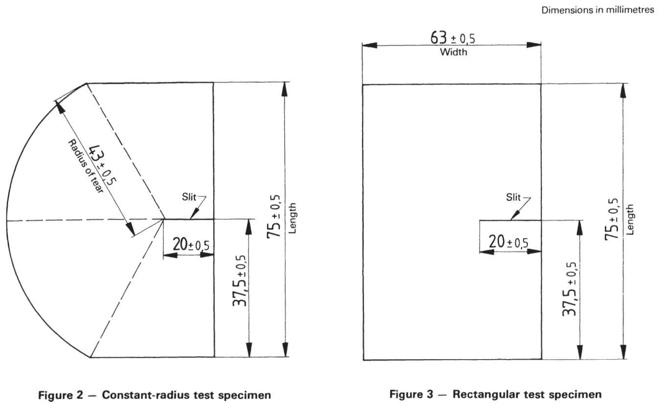
6.1 The test specimen shall have the shape and dimensions shown in figures 2 or 3. The preferred or referee specimen shall be the constant-radius specimen (figure 2) because of better reproducibility (see 8.5).
6.2 The test specimen may be cut from the sample using templates and a sharp knife. Special attention shall be given to the cutting of the 20 + 0,5 mm slit, which shall be free of nicks and ragged edges.
NOTE — Some testing machines have a permanent and integral knife by which the slit can be cut into the test specimen after mounting in the jaws of the machine. In such cases, the sharpness of this knife and its ability to cut the slit to the correct dimensions should be frequently checked.
6.3 Unless otherwise specified by the specification for the material being tested, five test specimens lor five groups of test specimens (see the note)1 shall be tested in each principal direction of the film sample, cut from positions evenly spaced across the width of the sample.
NOTE — In the case of films of low tear strength, it is permissible to test a group of two or more test specimens simultaneously in order to meet the requirements of 8.3. Cut the individual test pieces for each group adjacent to each other, but space the groups approximate evenly across the width of the sample. However, certain specimens in the same sandwich may tear obliquely in opposite directions, which may lead to falsely high results. When this testing behaviors is encountered, single specimens must be tested even though scale readings may be in the range below 20. For thin film, it is recommended that single specimens and a lower capacity tester be used rather than several specimens and a higher capacity machine.
6.4 When testing film in the machine (longitudinal) direction, test specimens shall be oriented so that their width is cut in the longitudinal direction and, similarly, specimens for transverse tear strength determinations shall be cut with their width in the transverse direction.
8 Procedure
8.1 Determine the thickness of the material being tested by the method specified in ISO 4591 and ISO 4593.
NOTE – ISO 4593 is not suitable for use with embossed film and sheeting.
8.2 Check that the Elmendorf apparatus is level. Lift and arrest the pendulum, set the indicating mechanism to the starting position and gently release the pendulum. Check that the pointer indicates zero and adjust if necessary according to the manufacturer’s instructions.
8.3 Carry out a few tests by the procedure specified in 8.4 to
check whether augmenting weights are required or a number of test specimens need to be tested simultaneously (see the note to 6.3) so that on any test the energy of the pendulum absorbed in tearing lies between 20 and 80 % of the total energy of the pendulum. Check the zero setting and adjust according to the manufacturer’s instructions each time that augmenting weights are fitted or removed.
8.4 Lift and arrest the pendulum of the machine and set the indicating mechanism to its starting point. Carefully position the test specimen, or group of test specimens, in the jaws of the grips so that the slit is centrally disposed between the fixed and movable jaws of the machine and tighten the clamps firmly (see the note). Carefully release the pendulum and read from the scale the force expended in tearing the specimen or group of test specimens.
NOTE — When the machine is fitted with an integral slitting knife, clamp the specimen as in 8.4 and then operate the knife to produce the slit (see the note to 6.2).
8.5 When constant-radius test specimens (see figure 2) are used, reject any tests in which the line or tear deviates outside the constant radius section and test additional specimens to replace those rejected.
When rectangular test specimens (see figure 3) are used, reject any tests in which the line of tear deviates more than 10 mm from the line of the slit, except when the tear is following a specific line of an embossed pattern, and test additional specimens to replace those rejected. When the tear deviation consistently exceeds 10 mm, use the constant-radius test specimens.
9 Calculation and expression of results
9.1 From the scale readings, determine, according to the machine manufacturer’s instructions, the force in newtons required to tear each test specimen, taking account of any use of augmenting weights and groups of specimens torn simultaneously. Record this force in newtons as the tear resistance of each test specimen.
9.2 Calculate the arithmetic mean tear resistance in each principal direction of the film or sheeting.
9.3 If required, calculate the standard deviation for each set of results.

Annex A
Adjustment and maintenance of the instruments
Follow the procedure described below for each of the pendulum/additional weight combinations used.
A.1 Inspection
Check the following items and make any necessary adjustments.
a) Check that the pendulum shaft is not bent.
b) Check that the distance between clamps is 2,8 + 0,3 mm and that when the pendulum is in its initial position, the clamps are in alignment.
c) Check that the knife fitting is secure, and that the cutting edge is sharp and undamaged. The blade shall be situated midway between, and at right angles to, the top of the clamps.
d) Ensure that the pointer is undamaged and rigidly attached to the sleeve.
A.2 Levelling
Mount the instrument on a rigid bench and, if possible, firmly attach it to the bench.
With the pendulum clamp closed, adjust the level of the instrument so that the pendulum hangs vertically and the index marks on the pendulum and base coincide. With the stop depressed, displace the pendulum slightly and after it comes to rest, check that the index marks still coincide.
A.3 Zero adjustment
After Ieveling, operate the instrument several times with clamps empty and closed to ascertain whether the pointer registers zero. If zero is not registered, move the adjustable pointer stop.
A.4 Pendulum friction
Make a reference mark on the stop mechanism 25 mm to the right of the edge of the pendulum catch. Raise the sector to its initial position and set the pointer so that it does not meet the pointer stop when the instrument is operated.
When the sector is released and the pendulum stop held down, the sector should make at least 35 complete oscillations before the edge of the sector which engages with the catch no longer passes to the left of the reference mark. Otherwise, clean, oil or adjust the bearing.
A.5 Tearing length
Adjust the position of the knife. Check that the tearing length is 43,0 + 0,5 mm. If this is not so, adjust the dimensions of the guillotme or template used.
Annex B
Calibration of the instrument
Calibration of the instrument may be checked by measuring the work done by the pendulum in raising various attached weights. The indicated scale reading is then compared with the amount of work done. Many tear testers are provided with a threaded hole to aid the attachment of weights.
The position of the centre of gravity of the attached weights should be known.
Set up the instrument and check it as specified in annex A. With various weights attached, operate the instrument without a test piece in position and determine the scale reading and height above a horizontal datum surface of the centre of gravity of the additional weight corresponding to this scale reading.
Calculate the correct scale readings Y from the formula
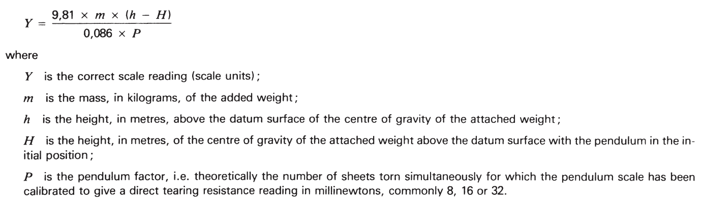
For routine calibration checks, an alternative procedure is to prepare a graph giving (h — H) for different scale readings. It is then only necessary to determine the scale reading for a given added weight, to read off the corresponding value of (h — H) and to calculate the error using this value.
Calculated and indicated scale readings should agree to within ± 1 % . if they do not, the fault should, if possible, be found and remedied. Otherwise, prepare a correction chart and adjust the results accordingly.

Function
The instrument computes the average tearing force of a cut specimen from the energy loss of a falling
pendulum. This test very well simulates the practical case where a test specimen is exposed to a sudden heavy load which causes the test specimen to tear, propagating an existing cut, such as a seam or a buttonhole.
The instrument digitally displays the average tearing force of a single test specimen, rounded to the nearest three digits. The displayed test result automatically considers the selected pendulum weight and the number of test specimens, thus eliminating the need for retroactive conversion.
Instead of a slave pointer, the instrument employs a digital optical encoder for measurement of the pendulum movement. This eliminates the usual friction, adjustment and maintenance problems and significantly improves the measuring accuracy of the instrument.
The instrument features an automatic calibration function which compensates for the pendulum friction and for any leveling error of the instrument. This further improves the measuring accuracy and eliminates the need for precise leveling of the instrument. Therefore, the instrument requires no spirit level.
The instrument is supplied with an ISO conform calibration certificate.
The instrument has been designed for easy handling and for maximum operator safety:
- By means of unique specimen clamps the test specimen is loaded to the instrument quickly and without appreciable force by simply flipping over two levers. This eliminates the cumbersome and sometimes painful tightening of conventional sample clamps.
- For the higher measuring ranges pendulum increment weights are used together on the twin pendulum.
- For changing of pendulum weights the pendulum can be locked in the horizontal position, and the pendulum weights can easily be pushed onto the pendulum and locked into place.
- To release the pendulum, both hands of the operator are required to prevent any interference with the swinging pendulum.
Testing
- Select test pieces: Select the test pieces in such a manner that they are representative of the lot to be
tested.
- Paper and non-Wovens: Sample the test piece in accordance with TAPPI T 400, DIN 53’101, ASTM D
5734 or any other appropriate standard. There shall be no folds, creases, or other visible defects in the area from which the test piece is cut and the test piece shall not include any part of the sample that is less than 15 mm from the edge of the sheet or reel. If watermarks are present, this should be stated in the test report. Cut sufficient test specimens to give a minimum of 10 valid test results in each required principal direction of the paper (e.g. a total of at least 40 specimens in each direction). Cut the test specimens with the die supplied with the instrument or with the template and the knife. In the latter case the dimensions of the test specimens are (63 ± 0,15) mm x (73 ± 1) mm. The edges of the test specimens shall run exactly parallel and perpendicular to the principal direction of the paper. Since the test specimens are torn perpendicularly to their longer side, the longer side must run parallel to the principal direction to be tested. - Woven Fabric: Cut a test piece approximately 70 cm long across the full width of the material to be tested. There shall be no folds, creases, or other visible defects in the area where the test piece is cut. Take no specimen nearer to the selvage than one-tenth the width of the fabric. Take warp specimens with different warp yarns in each specimen for a warp test and filling specimens that come from a different filling bobbin for a filling test. Take five specimens in either direction or take as many specimens as necessary to achieve a 95 % confidence interval of the test result of not more than 4 %. Cut the test specimens with the die supplied with the instrument, template, and knife. In the latter case the dimensions of the test specimens are (63 ± 0,15) mm x (73 ± 1) mm. The edges of the test specimens shall run exactly parallel to the yarns. Since the test specimens are torn perpendicularly to their longer side, the longer side of warp specimens must run parallel to the warp direction and vice versa.
- Condition test specimens: Prior to testing condition the test specimens in a standard atmosphere (20 °C ± 2 °C and 65 % ± 2 % relative humidity) in accordance with ASTM D 1776 or DIN 53,802 respectively.
- Switch on instrument: Switch on the instrument with the power switch located at the rear of the
instrument.
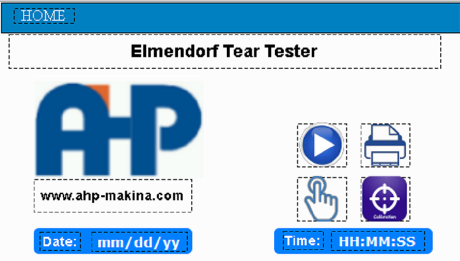


- After switch-on go to the calibration page because the instrument would not be functional without calibration. Therefore, at this point, the calibration program cannot be switched off.
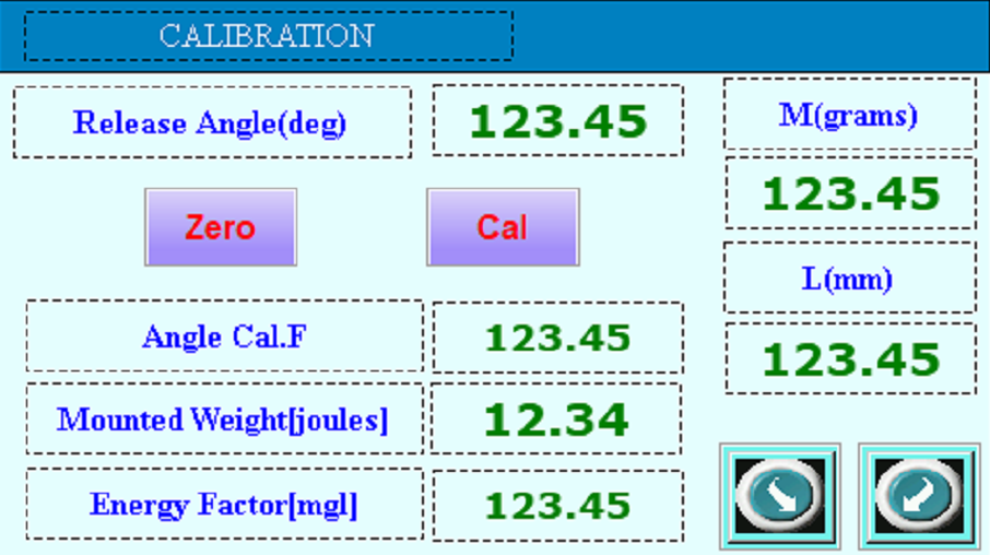
M(grams): Mounted mass
L(mm): Effective length of the pendulum. This is the standard value defined in the design of the machine. L is 64.3mm.
Release Angle (deg): The release angle of the pendulum is 67.5 degrees, which is the standard number for the machine’s design.

Using this key you can go to friction loss calculation page.

Back to main menu

Click then the pendulum is in zero position

Click when the pendulum is in the release angle
The above two keys “Zero” and “Cal” are for calibration of the angle of the pendulum according to the mass that is assembled.
Procedure for calibration: Bring the pendulum to the zero position and then click “Zero.” Enter the right value for mounted mass. Bring the pendulum to the release angle and click on “Cal.” Then, go to the measurement page of friction loss.
Friction-Loss Measurement:
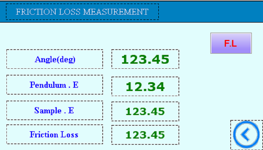
Bring the pendulum to the release point without any sample and then release it. You will see friction and loss value on “Sample. E”. Click on “F.L” key to save this value as friction loss of the machine.
- Determine measuring range: Determine the required measuring range MR according to the following algorithm:
MR = 2.5 · ATF · NOS
It is:
ATF = expected average tearing force of a single test specimen
NOS = number of test specimens torn simultaneously.
Select the pendulum weight, which comes closest to the required measuring range MR as determined by the above algorithm. The machine has the following tearing measuring ranges: 200 cN, 400 cN, 800 cN, 1,600 cN, 3,200 cN, 6,800 cN, 13,600 cN and 30,000 cN based on customer order.
- Load test specimen: Load the test specimen(s) to the sample jaws and close the jaws by flipping the flaps to the outside. Always close the movable jaw first and the fixed jaw second.
Carefully align the specimen(s) in the jaws with the bottom edge precisely set against the lower edge of the jaws. If more than one (paper) specimen is loaded, make sure all specimens are mounted in the same direction (machine direction or cross direction). - Slit specimen: Slit the test specimen(s) by pulling the knife lever down
- Start test: Release the pendulum by the key
- Visually check the tear: Visually check the test specimen(s) for proper tearing. If the test specimen is not completely torn, it is too strong for the pendulum weight(s) mounted to the pendulum. In this case, repeat the test with heavier pendulum weight. Paper: When testing paper, the path of the tear may deviate from the direction of the slit. If the mean deviation exceeds 10 mm in one or two of ten tests, reject these results and carry out further tests to bring the number of satisfactory tests up to 10. If in more than two of the test specimens the deviation exceeds 10 mm, include the results and state the fact in the test report. If, instead of tearing in the normal way, the paper of any test specimen peels apart to expose a wide band of torn surface (“skinning”), apply the above criteria to the mean center line of the torn band through the test specimen. Fabric: When testing fabric, reject readings are obtained where the specimen slips in the jaws or where the tear deviates more than 6 mm away from the projection of the original slit.
- Repeat the test up to 10 times and you will see average value on the test page
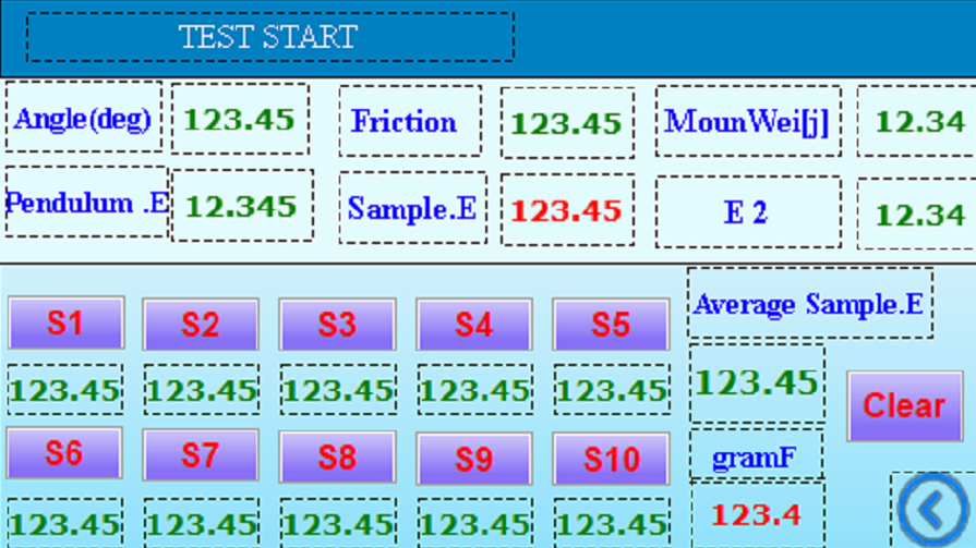
For measurements, first of all, click on “Clear” to clear all the last results. Bring the pendulum to the release angle. after releasing, the energy will be shown on Sample E and if you click on each of S1 to S1 the value will be saved. Average value of samples will be calculated for 10 pcs.
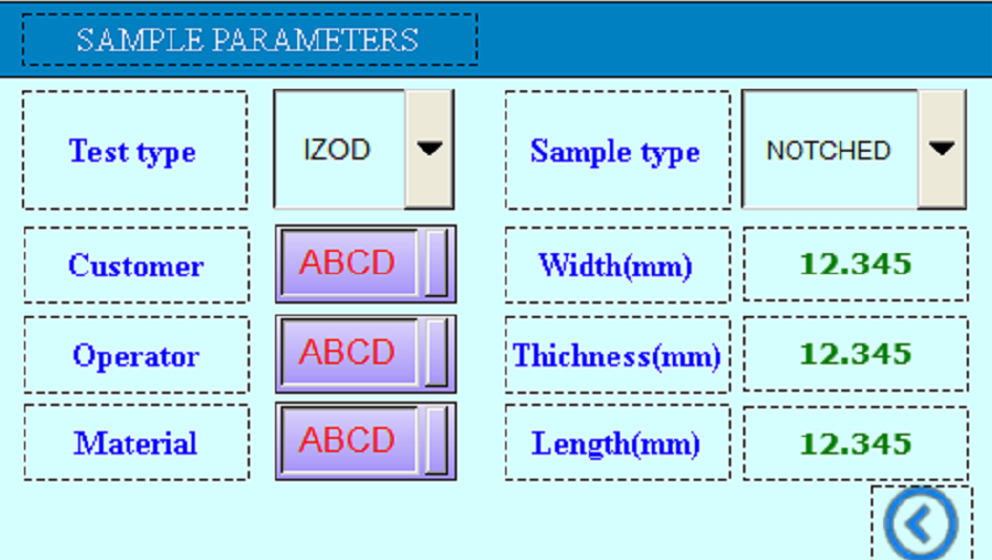
Sample parameters will be filled for printout and saving of data.
Saving of Test Data
in home page if you click on:

You will go to saving page:
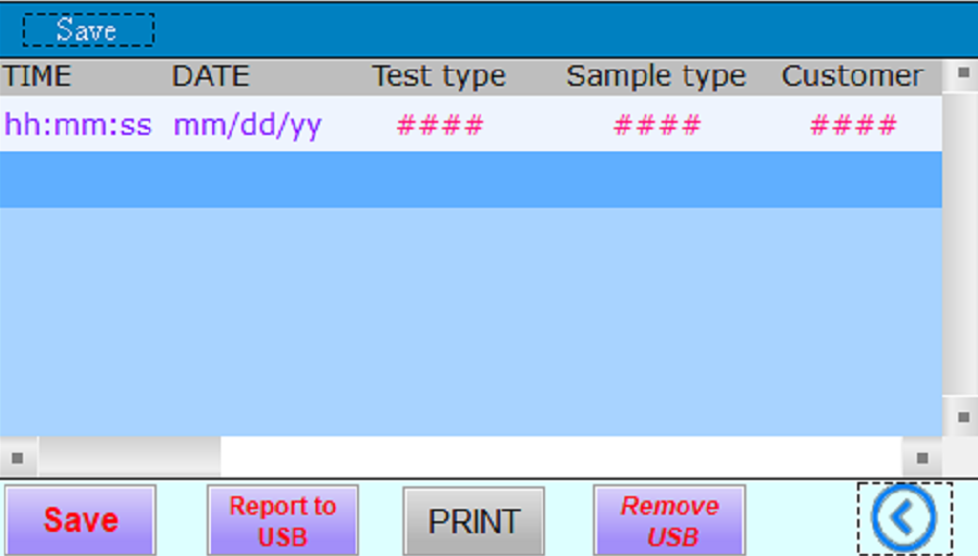
Clicking “Save”, will save a row of data including sample general parameters and test results. Clicking on “Print” will send the last results to the thermal printer. If you put the flash disk on the machine to USB slut, You can save all test data in the memory to the flash disk as MS EXCEL file. After saving of data you need to click on “Remove USB” to detach the flash disk.