
Comparing Different Types of Bend-Rebend Testing
ASTM A615
Bending Requirements
10.1 The bend-test specimen shall withstand being bent around a pin without cracking on the outside radius of the bent portion. The requirements for degree of bending and sizes of pins are prescribed in Table 3. When material is furnished in coils, the test specimen shall be straightened prior to placing it in the bend tester.
10.2 The bend test shall be made on specimens of sufficient length to ensure free bending and with apparatus which provides:
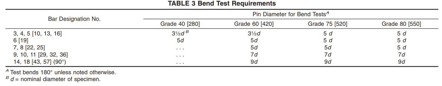
10.2.1 Continuous and uniform application of force throughout the duration of the bending operation. 10.2.2 Unrestricted movement of the specimen at points of contact with the apparatus and bending around a pin free to rotate.
10.2.3 Close wrapping of the specimen around the pin during the bending operation.
10.3 It is permissible to use more severe methods of bend testing, such as placing a specimen across two pins free to rotate and applying the bending force with a fixed pin. When failures occur under more severe methods, retests shall be permitted under the bend-test method prescribed in 10.2.
DIN EN 10080
Reinforcing steel cannot be ordered and/or supplied according to this standard. Reinforcing steel can only be supplied according to product specifications in which ‚technical classes‘ are set out (such specifications include European Standards, technical specifications, national standards – e.g. the new edition of the DIN 488 series of standards – or agreements issued by the building inspectorate). If the provisions of these product specifications are in agreement with the present standard, then products manufactured according to those specifications may bear the CE mark if they fulfil all the relevant requirements. A new edition of the DIN 488 series of standards is in preparation and will replace those standards listed in the supersedure statement.
DIN 488-2
7.3.3 Bend performance
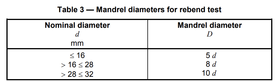
To demonstrate the bend performance, the rebend test shall be carried out according to DIN EN ISO 15630-1 for diameters up to d = 32 mm.
Bend the test pieces through an angle of at least 90° around a mandrel with a diameter as specified in
Table 3, age the test pieces (see DIN 488-6:2009-08, Table 21) and rebend them after cooling in still air to
room temperature of at least 20° C.
For diameters d = 40 mm, carry out a bend test with a mandrel diameter D = 6 d and a minimum angle of 90° according to DIN EN ISO 15630-1.
After the test, the test piece shall show no sign of fracture or cracks visible to a person with normal or
corrected vision.
DIN 488-3
7.3.4 Bend performance
To demonstrate the bend performance, the re-bend test shall be carried out according to DIN EN ISO 15630-1.
Bend the test pieces through an angle of at least 90° around a mandrel with a diameter D as specified in
Table 3, age the test pieces (see DIN 488-6:2009-08, Table 21) and re-bend them after cooling in still air to
room temperature of at least 20° C.
After the test, the test piece shall show no sign of fracture or cracks visible to a person of normal or corrected vision.

DIN EN ISO 7438
4 Test equipment
4.1 General
The bend test shall be carried out in testing machines or presses equipped with the following devices:
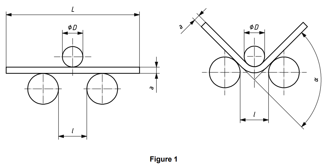
a) bending device with two supports and a former as shown in Figure 1;
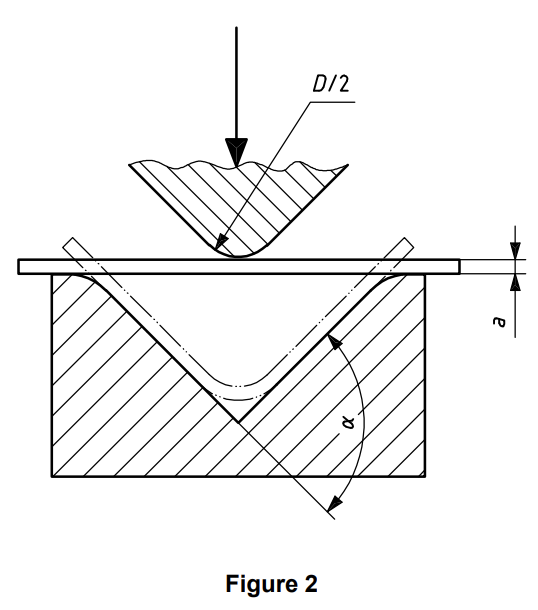
b) bending device with a V-block and a former as shown in Figure 2;
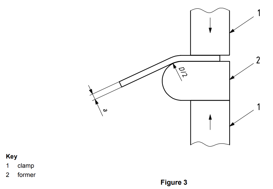
c) bending device with a clamp as shown in Figure 3.
4.2 Bending device with supports and a former
. . The length of the supports and the width of the former shall be greater than the width or diameter of
the test piece. The diameter of the former is determined by the product standard. The test piece supports and the former shall be of sufficient hardness (see Figure 1).
. . Unless otherwise specified, the distance between the supports, l, shall be:

and shall not change during the bend test.
4.3 Bending device with a V-block
The tapered surfaces of the V-block shall form an angle of 180° – alfa (see Figure 2). The angle is specified in the relevant standard.
The edges of the V-block shall have a radius between 1 to 10 times the thickness of the test piece and shall be of sufficient hardness.
4.4 Bending device with a clamp
The device consists of a clamp and a former of sufficient hardness; it may be equipped with a lever for
applying force to the test piece (see Figure 3).
Because the position of the left face of the clamp could influence the test results, the left face of the clamp (as shown in Figure 3) should not reach up to or beyond the vertical line through the centre of the circular former shape.
DIN EN ISO 15630-1
6 Bend test
6.1 Test piece
The general provisions in Clause 4 apply.
6.2 Test equipment
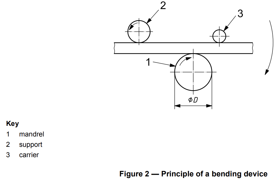
6.2.1 A bending device, the principle of which is shown in Figure 2, shall be used.
NOTE Figure 2 shows a configuration where the mandrel and support rotate and the carrier is locked. It is also possible that the carrier rotates and the support or mandrel is locked.
6.2.2 The bend test may also be carried out by using a device with supports and a mandrel (e.g. see ISO 7438).
6.3 Test procedure
The bend test shall be carried out at a temperature between 10 °C and 35 °C, unless otherwise agreed by the parties involved.
For testing at a low temperature, if the agreement does not specify all the testing conditions, a deviation of ±2 °C on the agreed temperature should be applied. The test piece should be immersed in the cooling
medium for a sufficient time to ensure that the required temperature is reached throughout the test piece (for example, at least 10 min in a liquid medium or at least 30 min in a gaseous medium). The bend test should start within 5 s from removal from the medium. The transfer device should be designed and used in such a way that the temperature of the test piece is maintained within the temperature range.
The test piece shall be bent over a mandrel.
The angle of bend (γ) and the diameter of the mandrel (D) shall be in accordance with the relevant product standard.
7 Rebend test
7.1 Test piece
The general provisions given in Clause 4 apply.
7.2 Test equipment
7.2.1 Bending device
A bending device as specified in 6.2 shall be used.
7.2.2 Rebending device
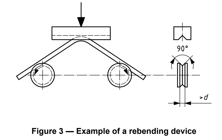
Rebending can be performed on a bending device as shown in Figure 2. An example of an alternative
rebending device is shown in Figure 3.
7.3 Test procedure
7.3.1 General
The test procedure consists of three steps:
a) bending;
b) artificial ageing;
c) rebending.
The test procedure is illustrated in Figure 4.
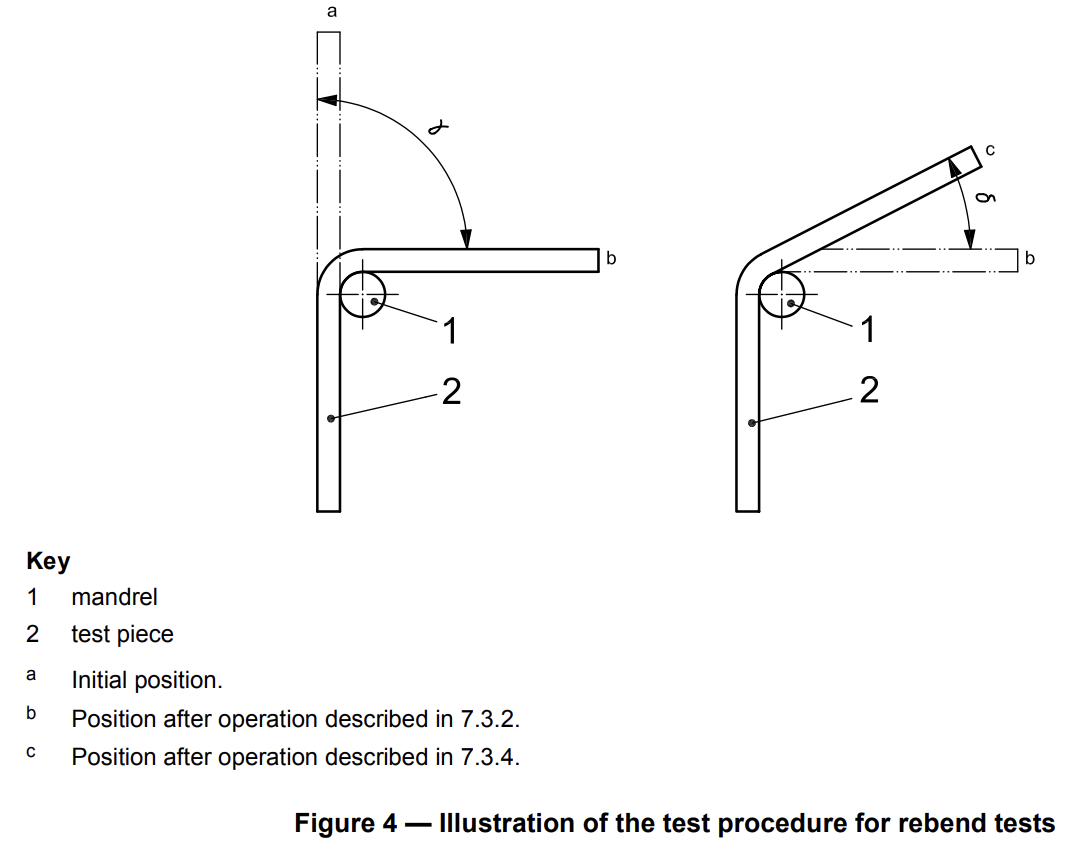
7.3.2 Bending
Bending shall be performed at a temperature between 10 °C and 35 °C. The test piece shall be bent over a
mandrel.
The angle of bend (γ) and diameter of mandrel (D) shall be in accordance with the relevant product standard.
The test piece shall be carefully inspected for cracks and fissures visible to a person with normal or corrected vision.
7.3.3 Artificial ageing
The temperature and time of artificial ageing shall be in accordance with the relevant product standard.
If the product standard does not specify any ageing treatment, the conditions specified in Clause 4 should be applied.
7.3.4 Rebending
After free cooling in still air to a temperature between 10 °C and 35 °C, the test piece shall be bent back by a specified angle (δ) in accordance with the relevant product standard.
How to start working with machine
- Connect main power to 3 phase-380V power line. make sure you used a ground connection (Maximum power is 6 KW). Use safety electrical elements on the main power line.
- After you connect the power line, set the 3 phase lines in such a way that motor runs clockwise when you turn the clockwise key ON. unless change two phase lines, in the main power line to have correct rotation.
- On the main panel you have control keys as below:
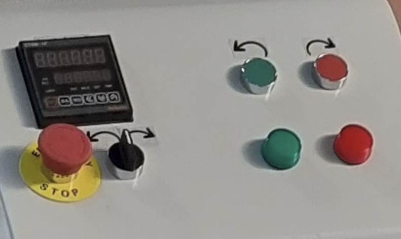
1- Manual rotations clockwise and counterclockwise
2- Angle indicator
3- Emergency switch
4- Clockwise and counterclockwise automatic rotation
For manual adjustment of the position of the rotating table, you can use manual rotation in two directions. Angle indicator showing the table angular position from the zero position. In any position of the rotating table, when you press the “ZERO” key on the indicator, you will set the zero position.
Angle indication on any direction will show positive on the display.
Just set the angle, and start the clockwise and counterclockwise keys to start movement. when it reaches the defined angle, it will be stopped automatically. When the indicator stops automatically for starting moving again manually, you need to press “RST” button on the indicator to reset the screen.
In any emergency situations, don’t forget to push the emergency key to shut the machine down.
- On the rotating table, there are holes for putting the loading pin on it. the proper hole will be selected based on the size of the bar. Also in the middle of the rotating table, there is template for bending the bar around that template. Choose proper template based on the size of the bar.
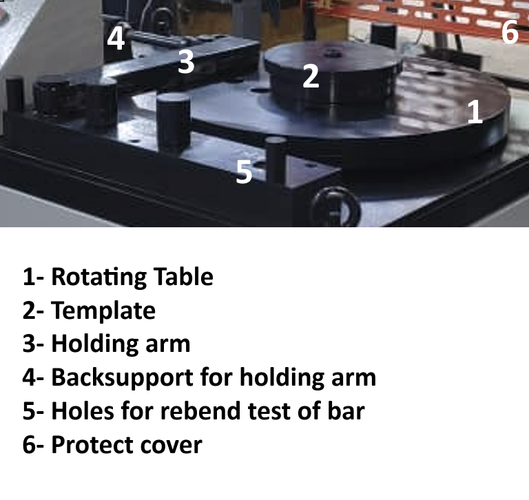
- After you set the proper template and position for the holding pin on the rotating table, you need to set the position for back support of the holding arm. remove the pin for back support to be able to move it freely. Then put the pins back and use the big nut on the neck of the back support to bring it in contact with the rebar. It will be a loose contact, not tight. Meaning using a hand to turn the nut to bring the back support in contact with the rebar will be enough.
- Bring the loading pin on the rotating table to be in contact with the rebar. it will be done using manual keys on the control panel with care. Do it slowly with care.
- Close the protective cover
- Start the automatic key to turn automatically in the requested direction and requested angle.
- After bending is done, using the manual key, release the force on the arm and remove the loading pin from the rotating table. Put the loading pin on the other side of the bent rebar and bring it in contact with the rebar using manual turn keys on the control panel. Set the proper position for the pin of the rebend test (No.5 of the above picture).
- Set the rebend angle to 20 degrees. and use the counterclockwise key on the control panel to turn it about 20 degrees.
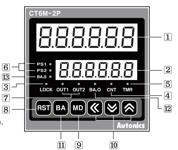
- Indicator Keys are as below:
Important Notes:
- Never use the machine with sizes larger than intended. The size table is laser-marked on the machine body. It may damage the machine motor, gearbox, Bearings and mechanical parts
- In setting the starting position of the sample, don’t forget to remove the loading pin from the rotating table.
- Never forget to close the protective lid when testing
- Don’t forget to grease the bearing intervals once a month
- For starting of the sample use manual keys very carefully
- Be careful of your hand when starting to rotate. Never touch the rotating table during rotation
- Only one man needs to work with the machine. Working with two people will have a high risk for the second person who is in contact with the rotating table
- Stand in front of the machine when testing a sample piece to have reach to the emergency switch in case of need
- Don’t leave the loading pins on the rotating table after testing is done. It will damage the machine if you don’t care; there is a loading pin on it. The loading pin may come in contact with the back support arm and damage it.