5 Apparatus
5.1 The test device may be constructed in different ways. In general, it consists of a horizontal test table, a sled, and a driving mechanism to produce a relative motion between the sled and the test table, regardless of which is the moving part.
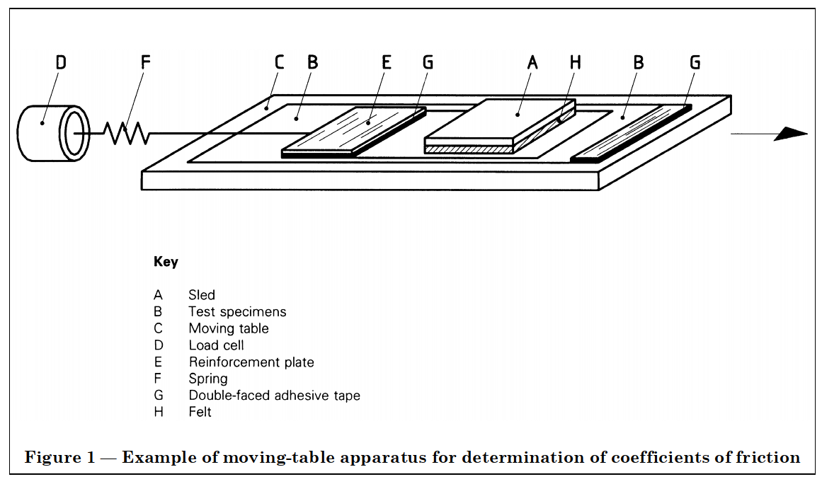
Figure 1 shows an example of apparatus in which the table is moved horizontally. The vertical motion of a tensile tester may also be utilized; in this case, the test table is fixed to the crosshead of the machine and the force is deflected to the horizontal direction by a pulley.
The force is recorded by a chart recorder or an equivalent electrical data-processing unit.
5.2 The test device shall comply with the following conditions.
5.2.1 The surface of the test table shall be flat and smooth, and made of a non-ferromagnetic metal.
5.2.2 The normal force shall be generated by a sled with a square-shaped contact base of 40 cm2 (edge length 63 mm). To ensure uniform pressure distribution, the base of the sled shall be covered with an elastic material, for example felt. The structure of this covering material shall be fine enough to avoid embossing thin films. The total mass of the sled shall be 200 g ± 2 g (exerting a normal force
of 1,96 N ± 0,02 N).
5.2.3 The motion that induces the friction process shall be free of vibrations and shall normally have a speed of 100 mm/min ± 10 mm/min.
In the case of specialist films or where difficulties are encountered, a speed of 500 mm/min ± 10 mm/min may be used. This shall be reported in Clause 11, item f).
5.2.4 The force-measuring system, including the recording instrument, shall not exceed an error of ± 2 %. Its transition time t99% shall not exceed 0,5 s. The pulling direction shall be in straight alignment with the frictional plane.
If the force-measuring system of a tensile tester is used, the transition time t99% shall be particularly checked, as the indicating systems of these machines are often rather inert.
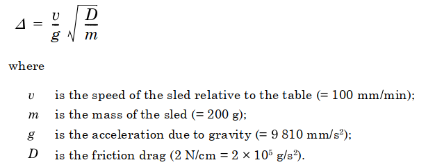
5.2.5 For the measurement of the static friction, the friction drag of the force-measuring system shall be adjusted to 2 N/cm ± 1 N/cm. This may be accomplished by using a suitable spring. For the measurement of the dynamic friction in the case of slipstick behaviour, this spring shall be replaced by a rigid connection.
NOTE The inertia of the mass of the sled induces an additional force at the start of the sled movement; thus the coefficient of friction differs from its true value by an amount ¹ given by:
6 Test specimens
For each measurement, two test specimens measuring about 80 mm × 200 mm are needed. At least three such pairs of test specimens taken from points uniformly distributed over the width of the sample, or the circumference in the case of tubular film, shall be tested.
Unless otherwise specified, the long axis, and thus the test direction, shall be parallel to the machine direction of the film.
When different frictional properties are expected for the two surfaces, front (1) and back (2), the two surfaces shall be identified and tested 1/1, 2/2 and/or 1/2 as agreed between the interested parties.
Extreme care shall be taken in handling the samples and specimens. The test surfaces shall be kept free of dust, fingerprints or any foreign matter that might change the surface characteristics.
NOTE 1 Testing of three pairs of test specimens represents a minimum for estimating the statistical tolerance interval. Depending on the intended precision and the homogeneity of the material under test, the number of specimens tested may have to be increased. ISO 2602:1980, Statistical interpretation of test results — Estimation of the mean — Confidence interval, gives guidance in this respect.
NOTE 2 To avoid contamination of the surfaces, several test specimens may be cut simultaneously and separated immediately before testing.
7 Conditioning
Unless otherwise specified, specimens shall be conditioned for at least 16 h in standard atmosphere 23/50 as defined in ISO 291 prior to testing.
8 Procedure
The following directions refer to an apparatus designed in accordance with Figure 1. If another equivalent apparatus is used, the appropriate procedure shall be followed. The testing shall be carried out in the same atmosphere as used for conditioning.
8.1 Measurement of film against film
8.1.1 Fix the right-hand end of the first test specimen on the test table with double-faced adhesive tape (or by a suitable clamp) so that the length axis of the test specimen coincides with that of the table. Reinforce the left-hand end of the second test specimen by attaching a small plate to it with double-faced adhesive tape. The mass of this plate shall not exceed 5 g. Connect this plate via a spring (see 5.2.5) to the load cell. Lay the second test specimen on the first and place the sled on top, gently and without shock, in the middle of the second test specimen (for films producing high blocking or other than frictional forces, the contact area, i.e. the size of the upper test specimen, shall be reduced as closely as possible to the area of the sled). Before starting the test, the apparatus shall be free of stress. After 15 s, start the motion of the test table and start up the recording instrument. The first force peak is caused by static friction.
8.1.2 After the first peak, oscillations in the force may sometimes occur. In this case, the oscillating part of the graph cannot be used to determine the dynamic coefficient of friction. The dynamic coefficient shall be determined by a separate measurement in which slipstick behaviour is eliminated by replacing the spring with a rigid connection.
This type of determination cannot be used to determine the static coefficient of friction because of the inertia error (see note in 5.2.5).
NOTE The load cell may also be attached directly to the sled. In this case, the second test specimen is fastened to the front edge of the sled with double-faced adhesive tape. However, this procedure is not advisable for stiff films since the bending moment may cause an unequal pressure distribution.
8.2 Measurement of film in contact with metal or another material
If the frictional behaviour of a film in contact with a metal surface or the surface of another material is to be determined, the lower test specimen (see Figure 1) shall be replaced by a specimen of the material in question. Otherwise, the same procedure shall be used.
The coefficients of friction determined in this way are dependent on the type of material as well as on its surface finish.
If subsequent measurements are made on the same test specimen of a material, it should be noted that abrasion may have occurred, which will change the surface properties. Also, the possibility of transfer of slip or antislip agent shall be considered.
9 Expression of results
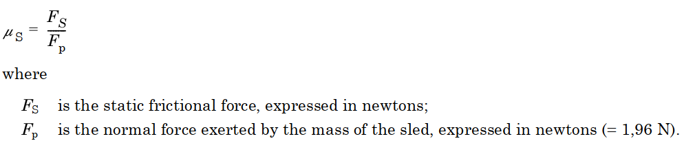
9.1 Static coefficient of friction
The force increases linearly to a maximum which represents the static frictional force FS. Measurements made at a high friction drag (i.e. without a spring) permit the dynamic coefficient of friction to be calculated, but not the static coefficient of friction (see 8.1.2).
The static coefficient of friction þS is given by the equation
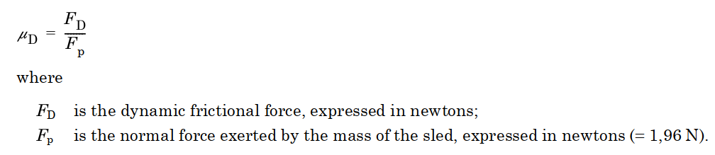
9.2 Dynamic coefficient of friction
The frictional force acting during the sliding motion often differs from the constant value which would exist in an ideal situation due to secondary effects related to increasing path length.
The dynamic frictional force FD is the average force over the first 6 cm of movement after the start of relative movement between the surfaces in contact, neglecting the static force peak FS. The dynamic coefficient of friction þD is calculated from the dynamic frictional force using the equation: