
Scope
This standard specifies a method for testing the resistance of joints to pressure cycling. It is applicable to piping systems based on rigid or flexible thermoplastics pipes intended to be used in hot and cold water applications.
3 Apparatus
3.1 Pressurizing device, capable of applying and regulating the water pressure in the test piece to a sinusoidal form between pressure limits as specified in the referring standard.
NOTE: It may be necessary to compensate for any differences between the pressure at the position of the test piece and the pressure indicated at any other measuring point.
3.2 Pressure measurement device, capable of measuring the water pressure in the test piece with an accuracy of ±5 %. The measurement device shall be capable of producing a record of the
sinusoidal wave form.
NOTE: It may be necessary to compensate for any differences between the pressure at the position of the test piece and the pressure indicated at any other measuring point.
3.3 Test chamber, capable of maintaining the specified test temperature within ±1 °C, unless testing in the range (23 + 5) °C, in which case the permitted deviations shall be +2 °C.
3.4 Thermometer(s), capable of checking conformity to the specified test temperature (see 3.3).
3.5 End-sealing device, of appropriate size and sealing method, for sealing the non-jointed end of the test piece. The device shall be restrained in a manner that does not exert longitudinal forces on the joints.
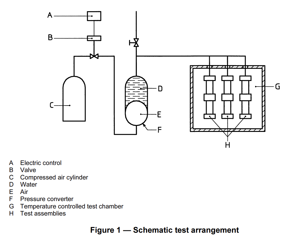
3.6 A typical test arrangement is shown in Figure 1.
4 Test pieces
4.1 Preparation
The test piece shall comprise an assembly of pipes and at least one fitting joined in accordance with
the manufacturer’s recommended practice.
The free length on each side of the fitting under test shall be not less than either 1,5d, or 300 mm, whichever is the greater, where d, is the nominal outside diameter of the pipe.
In order to include the required number of pipes and fitting(s), several test pieces may be tested simultaneously provided that the failure of one test piece does not affect the others under test.
6 Procedure
6.1 As specified in the referring standard, apply alternately to the test piece the two internal pressures and maintain the cycle frequency and test temperatures accordingly.
6.2 During and on completion of the number of cycles specified by the referring standard, inspect all joints for any sign of leakage, and record the wave form at regular intervals.
6.3 If leakage occurs prior to completion of the number of cycles specified by the referring standard, record the number of elapsed cycles and the position and nature of the leak.
Pressure Cycling Tester According to EN 12295
- Test cabin is an air or water tank as per customer request (basic model is air cabin)
- Pressure range 0-24 bar (other ranges as per customer request)
- Number of stations as per customer request (Basic machine has one pressure level with 3outlets-3 outlets have same pressure)
- The control panel is PC-PLC based
- Including software for monitoring and graphing of data
- Export of report in MS-WORD
- According to EN 12295
- Automatic pressure adjustment
- Air input for pneumatic system (8 bar)
- Systems include Air-Water cylinders of ratio 3 (other rations as per customer request)
- Basic model of test cabin is room temperature (chiller and heating could be connected as per request)
- Sample cabin size is 60*60*60 cm (other sizes as per customer request)
- Connections inside sample cabin is quick coupler
- Pressure is applied by air-water cylinder
- Pneumatic door for sample cabin
- Connection to computer is USB port
- Leak detection sensor inside test cabin (Whenever leak occurred in sample test will be stopped automatically)
- Computer and monitor is included
- Pressure applied to samples by water
- 3 stage water filter is included
- Software is included
- End caps for samples as per customer request will be quoted separately
Optional accessory 1 – Heating and circulation systems for sample cabin
Optional accessory 2- SS304 end caps