

Test Principle and Bending Geometry
The EN 1109 test determines the resistance of bituminous waterproofing sheets to cracking when subjected to controlled bending at low temperature.
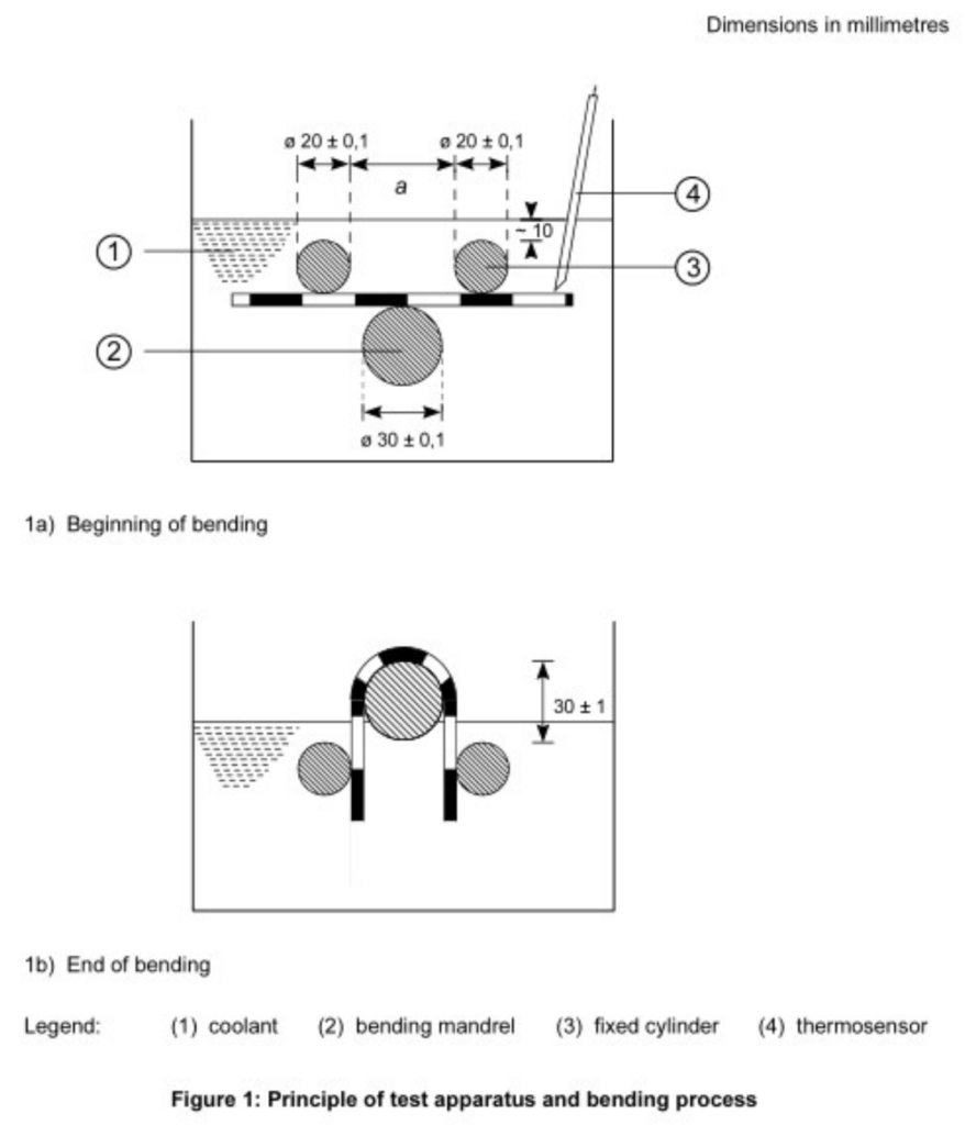
As illustrated in Figure 1, the bending system consists of two stationary, non-rotating cylinders positioned above a vertically moving bending mandrel. The test specimen is initially positioned horizontally between these components and completely immersed in the temperature-controlled coolant.
The main bending components are:
- Two fixed cylinders: Ø20 ± 0.1 mm
- Moving bending mandrel: Ø30 ± 0.1 mm
- Adjustable distance between the fixed cylinders
- Vertical mandrel travel
- Temperature sensor positioned approximately at specimen level
- Complete bending assembly immersed in the coolant
At the beginning of the test, the bending mandrel is located below the specimen. During testing, the mandrel travels vertically upward and contacts the underside of the specimen. Continued upward movement forces the specimen between the two fixed cylinders and progressively wraps it around the Ø30 mm mandrel.
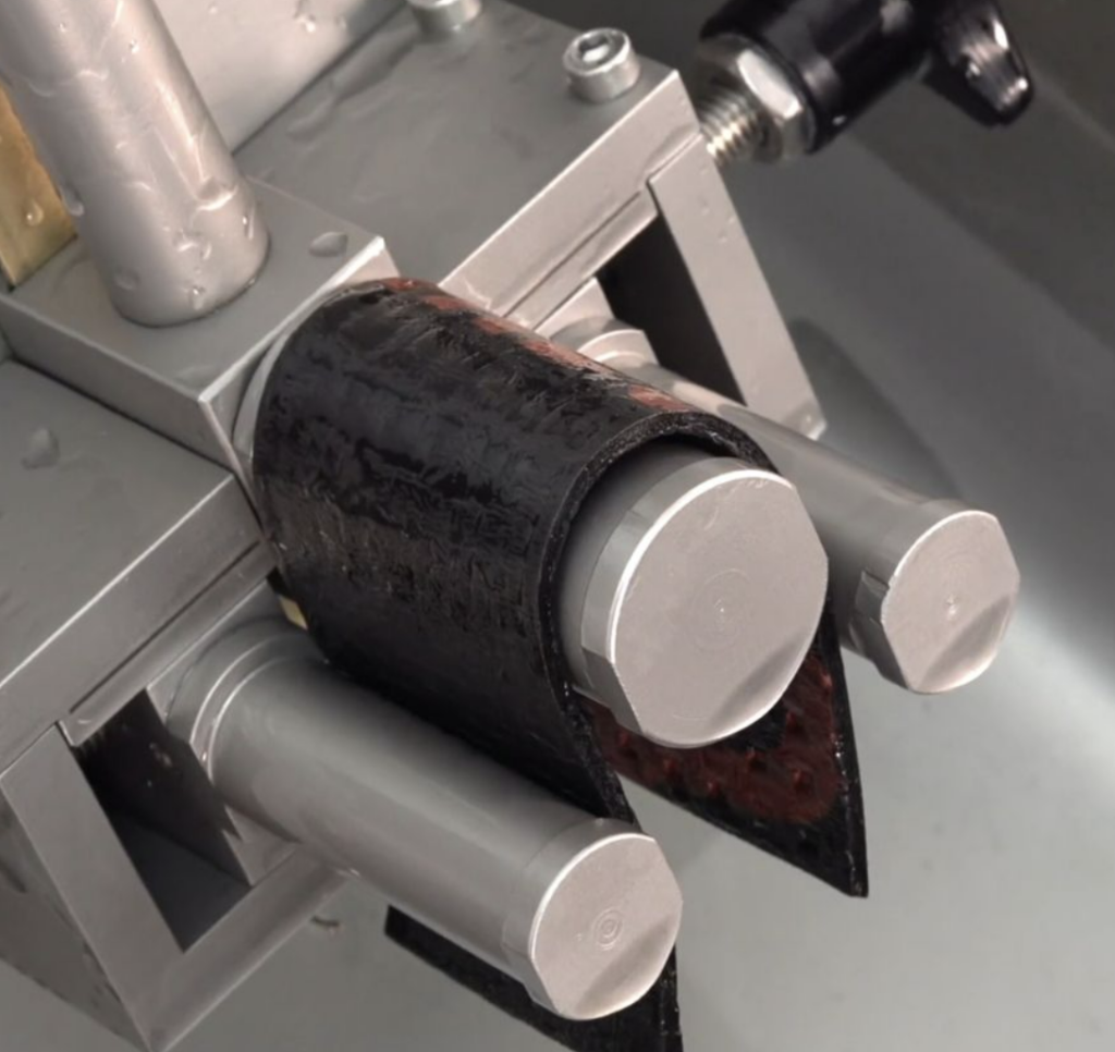
At the end of the movement, the specimen has been bent through approximately 180°.
The configuration shown in Figure 1 of the standard is particularly important because the test is not simply a free-bending test. The specified cylinder diameters, mandrel diameter, spacing, travel and speed establish a reproducible bending geometry and therefore form part of the controlled test conditions.
Adjustment of the Bending Assembly
Before starting a test series, the spacing between the two fixed cylinders must be adjusted according to the actual thickness of the specimen.
According to EN 1109, the distance a shown in Figure 1 is adjusted to approximately:
a = 32 mm + specimen thickness
This adjustment is important because specimens of different thicknesses require different cylinder spacing to maintain the intended bending geometry.
After adjustment, the complete bending mechanism is positioned in the refrigerant bath. The top of the fixed cylinders should be approximately:
10 mm below the surface of the coolant
The bending mandrel must be in its lowest position before the specimen is introduced for testing.
Temperature Control at the Specimen Position
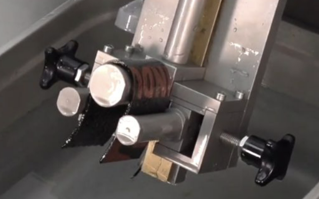
The complete bending process takes place while the specimen and bending mechanism are immersed in the coolant.
The thermostatic bath shall be capable of operation between:
+20°C and −40°C
with temperature control to the nearest:
0.5°C
EN 1109 additionally requires a separate temperature-measuring device capable of measuring to 0.5°C.
The temperature sensor is not positioned arbitrarily in the bath. As shown in Figure 1, it is placed in the test medium approximately at the same vertical level as the test specimen.
This arrangement allows the actual coolant temperature in the immediate test zone to be verified rather than relying only on the temperature indicated by the refrigeration controller.
Specimen Preparation
The standard test specimen has dimensions of:
140 ± 1 mm × 50 ± 1 mm
The specimens are taken uniformly across the width of the waterproofing sheet, with the longitudinal direction of each specimen corresponding to the production direction of the sheet.
Specimens should not be taken within approximately:
150 mm from the sheet edges
Each specimen is consecutively numbered, starting from one edge of the sheet, and the upper and lower surfaces are identified.
Where a removable protective film is present, it must be removed before testing without damaging the bituminous coating.
The standard describes removal using adhesive tape after cooling the specimen. Alternatively, compressed air may be used, with approximately:
- Maximum pressure: 5 bar
- Nozzle diameter: approximately 0.5 mm
If these methods cannot remove the film, a gas flame may be used only for the minimum time required to destroy the film without otherwise damaging the specimen.
Preconditioning Before Low-Temperature Exposure
After preparation, specimens are conditioned for at least:
4 hours at 23 ± 2°C
The specimens are placed on a flat support and must not touch one another.
They must also not adhere to the supporting surface. Where necessary, siliconized paper may be used between the specimen and the support.
Loose surface granules should be removed carefully by hand before testing.
Conditioning in the Cooling Bath
Before inserting the specimens, the coolant is brought to the required test temperature.
Once the specified temperature has been reached to the nearest 0.5°C, the specimens are placed into suitable holding devices at approximately the same height as the fixed cylinders.
The holders must:
- Keep the specimens flat;
- Maintain complete immersion;
- Prevent unnecessary contact between specimens;
- Allow free circulation of coolant around the specimens.
Insertion of specimens can temporarily increase the bath temperature. Therefore, the specified conditioning time does not simply start immediately after specimen insertion.
The specimens are conditioned for:
1 h ± 5 min
measured from the time at which the coolant has returned to the specified test temperature.
This detail is important for reproducibility because all specimens must experience essentially the same thermal conditioning before bending.
Testing the Upper and Lower Surfaces
The flexibility test is performed separately for the two surfaces of the waterproofing sheet.
For a specified test temperature, two series are prepared:
5 specimens for the upper surface + 5 specimens for the lower surface
Therefore, a complete evaluation at one specified temperature normally involves 10 specimens.
For each test, the specimen is positioned successively between the bending mandrel and the two fixed cylinders with the surface to be evaluated facing upward.
This orientation is essential because the upper and lower surfaces of a bituminous sheet may contain different coatings, surface finishes or structural arrangements and can therefore exhibit different low-temperature bending behavior.
Controlled Bending Sequence
Once the conditioned specimen is correctly positioned, the bending cycle is initiated.
The Ø30 mm mandrel travels upward from below the specimen at a nominal speed of:
360 mm/min
Throughout the bending operation, the actual travel speed must remain within:
360 ± 40 mm/min
The upward-moving mandrel first contacts the underside of the specimen and then forces the specimen upward between the two Ø20 mm fixed cylinders.
As the mandrel continues to rise, the specimen progressively conforms to the cylindrical surface of the mandrel.
The movement continues until the mandrel reaches:
30 ± 1 mm above the fixed cylinders
At this position, the specimen has been bent through approximately 180°, corresponding to the final configuration illustrated in Figure 1(b) of EN 1109.
Suitable limit switches are required to restrict the travel and provide a repeatable final bending position.
Coolant Level During Bending
The specimen must remain properly immersed throughout the test.
During upward movement of the mandrel, displacement of the specimen and mechanism can affect the coolant level. EN 1109 therefore requires the specimen surface to remain sufficiently below the coolant surface.
If necessary, the liquid level must be adjusted accordingly.
This ensures that the specimen is not unintentionally exposed to warmer ambient air during the actual bending operation.
Time Between Bending and Crack Inspection
After completion of the bending cycle, inspection must be performed rapidly.
The specimen shall be examined:
within 10 seconds after completion of bending
The short inspection interval minimizes changes in specimen condition caused by warming after removal from the low-temperature environment.
The specimen is examined against a suitable light source using the naked eye. Additional optical aids may be used when necessary.
Definition of Failure / Crack
The acceptance decision is based on the presence or absence of cracks in the tested coating.
For a reinforced bitumen sheet, a crack is considered to exist when one or more fissures in the coating extend as far as the reinforcement.
For an unreinforced sheet, the fissure must extend completely through the sheet.
Minor superficial marks that do not meet the standard’s definition of a crack should therefore not automatically be classified as failure.
Testing Sequence at a Specified Temperature
For each surface, all five specimens should be tested successively under the same controlled conditions.
Where the dimensions of the apparatus permit, EN 1109 allows several specimens to be tested simultaneously.
The sequence can be summarized as:
1. Prepare specimens → 2. Precondition at 23 ± 2°C → 3. Stabilize coolant → 4. Immerse specimens → 5. Condition for 1 h ± 5 min after temperature recovery → 6. Position specimen → 7. Bend at 360 ± 40 mm/min → 8. Stop at 30 ± 1 mm above cylinders → 9. Inspect within 10 s → 10. Record crack/no-crack result
Acceptance Criteria
At a specified temperature, the test for one surface is considered passed when:
at least 4 out of 5 specimens show no cracks.
The results for the upper and lower surfaces are evaluated and reported independently.
Consequently, a product may show different low-temperature flexibility behavior on its two surfaces.
Determination of Cold Bending Temperature
EN 1109 also provides a systematic procedure for determining the limiting cold bending temperature when the value is not already known.
Stage 1 – Preliminary Temperature Range
The approximate range is first determined using individual specimens.
Testing is carried out at temperature intervals of:
6°C
starting around the expected cold bending temperature.
The selected test temperatures are therefore multiples of 6°C, for example:
−12°C, −18°C, −24°C, etc.
This preliminary stage identifies the temperature range in which the transition from acceptable to unacceptable bending behavior occurs.
Stage 2 – Fine Determination
After the approximate range has been established, a more precise determination is carried out using series of five specimens.
Testing begins at the highest temperature within the identified range.
The temperature is then reduced in increments of:
2°C
A new series is tested at each temperature.
This step-by-step reduction continues until the first temperature is reached at which:
two or more specimens out of five show cracks.
The previous 2°C temperature step, at which at least four specimens showed no cracks, is designated as the cold bending temperature.
Example of the Evaluation Logic
If the results are:
−18°C → 5/5 without cracks
−20°C → 4/5 without cracks
−22°C → 3/5 without cracks
the reported cold bending temperature would be:
−20°C
because −22°C is the first temperature at which at least two specimens fail, while at the preceding temperature at least four of the five specimens successfully passed.
The upper and lower surfaces are evaluated separately and may therefore have different reported cold bending temperatures.
Critical Test Parameters
For reliable testing according to EN 1109, the following parameters directly influence the test conditions and must therefore be controlled:
| Parameter | EN 1109 Requirement |
|---|---|
| Fixed cylinder diameter | 20 ± 0.1 mm |
| Bending mandrel diameter | 30 ± 0.1 mm |
| Cylinder spacing | Approx. 32 mm + specimen thickness |
| Cooling bath range | +20°C to −40°C |
| Temperature resolution/control | 0.5°C |
| Specimen dimensions | 140 ± 1 × 50 ± 1 mm |
| Preconditioning | ≥ 4 h at 23 ± 2°C |
| Low-temperature conditioning | 1 h ± 5 min after temperature recovery |
| Mandrel travel speed | 360 ± 40 mm/min |
| Final mandrel position | 30 ± 1 mm above fixed cylinders |
| Approximate bending angle | 180° |
| Inspection time | Within 10 s after bending |
| Specimens per tested surface | 5 |
| Acceptance criterion | At least 4 of 5 without cracks |
| Preliminary temperature interval | 6°C |
| Final determination interval | 2°C |
Functional Requirements of the Test Apparatus
From an equipment-design perspective, compliance with the EN 1109 test method requires more than simply achieving a low temperature.
The apparatus must reproduce the specified thermal and mechanical test conditions in a controlled and repeatable manner.
The essential functional requirements therefore include:
- Stable refrigeration over the required +20°C to −40°C range;
- Measurement of the actual coolant temperature at specimen level;
- Full immersion of the bending mechanism and specimens;
- Correct Ø20 mm fixed-cylinder geometry;
- Correct Ø30 mm bending-mandrel geometry;
- Adjustable cylinder spacing for different sheet thicknesses;
- Controlled vertical movement of the bending mandrel;
- Mandrel speed maintained at 360 ± 40 mm/min;
- Repeatable final travel position of 30 ± 1 mm;
- Suitable travel limit switches;
- Specimen holders that allow free coolant circulation;
- Sufficient working space for correct specimen positioning;
- Reliable execution of repeated bending cycles under identical conditions.
By controlling these parameters, the apparatus enables reproducible determination of both flexibility at a specified low temperature and the cold bending temperature of bituminous waterproofing sheets in accordance with EN 1109.
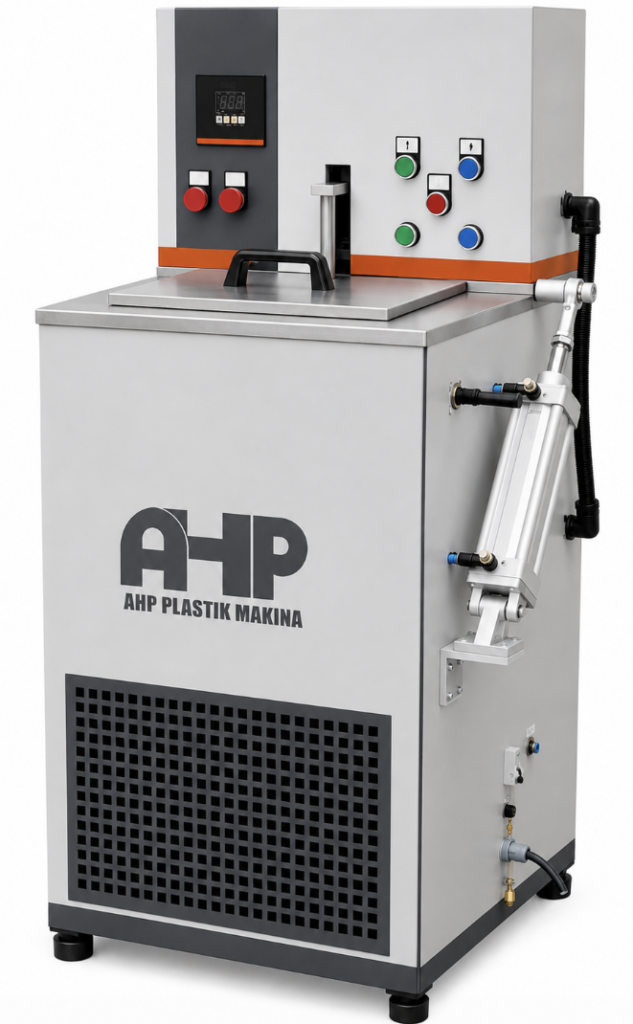
Cold Bending Tester for Bitumen Sheets According to EN 1109
Used to determine flexibility and cracking resistance of bitumen sheets at low temperatures. Used to determine minimum bending temperature in cold environment.
- Specimen Dimensions: 50 x 140 mm
- Lower sample bending roller: Ø 30 ± 0.1 mm
- Test speed: 360 ± 10 mm/min.
- Operating voltage: 220 Volt 50 Hz.
- Upper Rollers (rotateable): Ø 20 ± 0.1 mm
- Air input: 3 – 6 bar.
- Temperature range: -20°C to ambient (Other ranges as option)
- Sample thickness adjustment on upper rollers
- Test while samples is immersed
- Pneumatic lifting system for the test apparatus to get out of the liquid for easier observation
- SS304 material for parts in contact with liquid
- Outer chassis is electrostatic powder coated
- Cooling unit included
- Internal dimensions of bath: 298 x 327 x 200 mm