3 Concepts
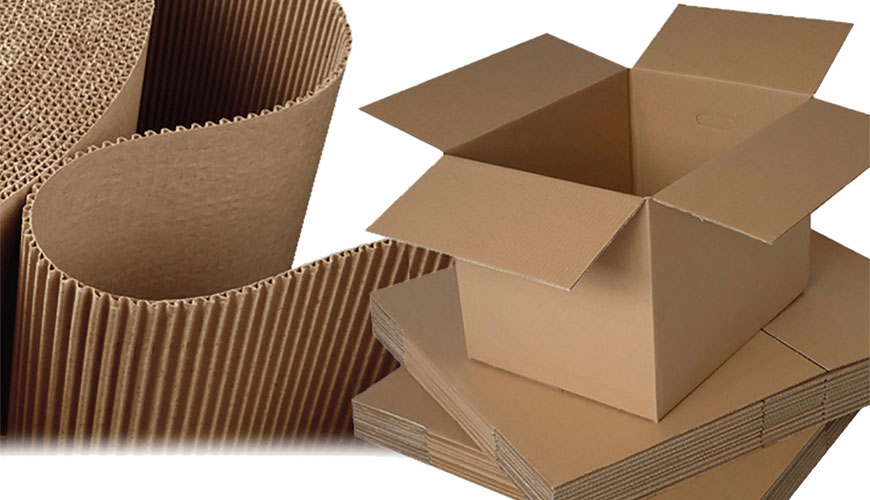
3.1 Corrugated fibreboard
Board consisting of one or more sheets of fluted paper glued to or between one or more sheets of paper or board (facing) (from DIN 6735).
3.2 Single-wall corrugated fibreboard
Board consisting of one sheet of fluted paper interposed between, and glued to, two facings (from DIN 6730).
3.3 Multiple wall corrugated fibreboard
Board consisting of two or more sheets of fluted paper interposed between, and glued to, three or more facings.
4 Types of corrugated fibreboard and flute sizes
4.1 Types of corrugated fibreboard
Corrugated fibreboard can be single-wall or multiple-wall. In the latter case, various combinations of different flute sizes are possible; those shown in figures 1 to 3 are examples only.

4.2 Flute sizes
Different flute sizes and combinations of sizes may be used in corrugated fibreboard. Flutes are classified
according to their height and pitch, as shown in figure 4 and table 1.

5 Requirements
5.1 Properties
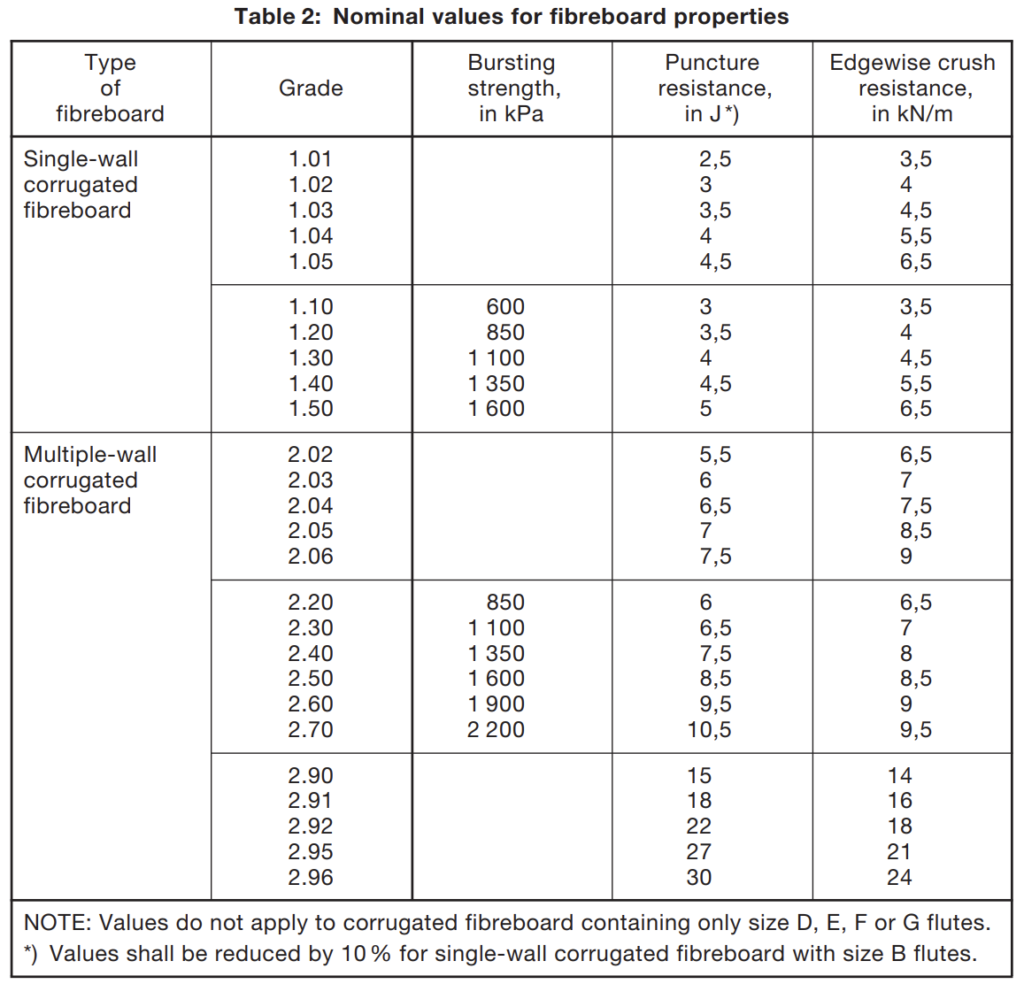
Corrugated fibreboard of grades 1.01 to 1.05 and 2.02 to 2.06 are primarily intended for storage purposes and are characterized by their puncture resistance and edgewise crush resistance.
Corrugated fibreboard of grades 1.10 to 1.50 and 2.20 to 2.70 are intended to be used for transport purposes as well, and are characterized by their bursting strength, puncture resistance and edgewise crush resistance. Corrugated fibreboard of grades 2.90 to 2.96 are considered as heavy duty board and are characterized by their puncture resistance and edgewise crush resistance.
5.2 Limiting values
Table 2 specifies nominal values for corrugated fibreboard properties. The mean value obtained when testing shall not drop below the nominal value by more than 7,5% in the case of bursting strength, 6% in the case of puncture resistance, and 5% in the case of edgewise crush resistance.
6 Designation
6.1 General
The designation of corrugated fibreboard shall refer to this standard and include the grade as specified in table 2 and the flute size as specified in table 1.
6.2 Examples
Designation of grade 1.20 single-wall corrugated fibreboard with size A flutes:
Corrugated fibreboard DIN 55468 – 1.20 A
Designation of grade 2.06 double-wall corrugated fibreboard with size B and size C flutes:
Corrugated fibreboard DIN 55468 – 2.06 BC
Designation of grade 2.95 triple-wall corrugated fibreboard with size B, size A and size A flutes:
Corrugated fibreboard DIN 55468 – 2.95 BAA
7 Testing
7.1 Sampling
Sampling shall be carried out as specified in DIN EN ISO 186.
7.2 Conditioning
Specimens shall be conditioned as specified in DIN EN 20187.
7.3 Bursting strength
Bursting strength shall be tested as in DIN EN ISO 2759.
7.4 Puncture resistance
Puncture resistance shall be tested as in DIN 53142-1.
7.5 Edgewise crush resistance
Edgewise crush resistance shall be tested as in DIN EN ISO 3037.
DIN EN ISO 2759 Determination of bursting strength
5 Apparatus
The apparatus shall contain, as a minimum, the features described in 5.1 to 5.4.
5.1 Clamping system, for clamping the test piece firmly and uniformly between two annular, plane, parallel surfaces which shall be smooth (but not polished) and grooved as described in annex A, which also gives the dimensions of the clamping system.
One clamping plate shall be held in a swivel joint or similar device so as to ensure that the clamping pressure is distributed evenly.
Under the load used for testing, the circular openings in the two clamping plates shall be concentric to within 0,25 mm and the clamping surfaces shall be flat and parallel. The method of checking the clamps is given in annex B.
The clamping system shall be capable of applying a clamping pressure in the range 700 kPa to 1 200 kPa and shall be constructed in such a way that repeatable clarnping pressures can be obtained in use (see annex C).
In calculating the clamping pressure, the reduction in area due to the grooves shall be ignored.
Any clamping-pressure-indicating device fitted should preferably be scaled to indicate the actual clamping pressure, not the pressure in the clamping system itself. The clamping pressure may be calculated from clamping-force and clamp-area information.
5.2 Diaphragm, circular, of natural or synthetic rubber, free from filler or loading, clamped securely with its outer surface, when at rest, recessed about 5,5 mm relative to the outer plane of the diaphragm-mounting plate.
The material and construction of the diaphragm shall be such that the pressures required to bulge the diaphragm outside the outer plane of the diaphragm plate are as follows:
— bulge height: 10 mm -E- 0,2 mm, pressure range: 170 kPa to 220 kPa;
—- bulge heiaht: 18 mm ± 0,2 mm, pressure range: 250 kPa to 350 kPa.
Diaphragms in use shall be regularly checked and changed if the bulge-height requirements are no longer met.
5.3 Hydraulic system, to apply an increasing hydraulic pressure to the inside of the diaphragm until the test piece bursts.
The pressure shall be generated by a motor-driven piston forcing a suitable liquid (e.g. pure glycerol, ethylene glycol containing corrosion inhibitor or low viscosity silicone oil) which is compatible with the diaphragm material against the inner surface of the diaphragm. The hydraulic system and the fluid used shall be free from air bubbles. The pumping rate shall be 170 ml/min -1 15 ml/min.
5.4 Pressure-measuring system, to measure bursting strength.
It may employ any principle which produces a measurement and display accuracy equal to ± 10 kPa or ± 3 % of the measurement, whichever is the greater. The rate of response to the rising hydraulic pressure shall be such that the indicated maximum pressure is within ± 3 % of the true peak pressure as determined by a calibration system of the type described in annex D.
8 Procedure
Tests shall be carried out in the standard atmosphere, defined in ISO 187, used for the conditioning of test pieces in accordance with clause 7.
If required, determine the grammage in accordance with ISO 536. Prepare the apparatus for use in accordance with the manufacturer’s instructions and the requirements of this International Standard. Electronic instruments may require a “warm-up” period.
Where alternative measuring pressure ranges are available, select the most suitable range, if necessary by carrying out a preliminary test using the highest available range.
Adjust the clamping system to give the lowest clamping pressure within the range 700 kPa to 1 200 kPa which prevents slippage of the test piece. A guide to clamping pressures which have proved satisfactory for materials of various bursting strengths is given in Table 1.

Raise the clamp and insert the test piece in a position enabling the full clamping area to be used, then apply the full clamping pressure to the test piece.
If necessary, zero the hydraulic-pressure-indicating device according to the manufacturer’s instructions. Apply hydraulic pressure until the test piece bursts. Retract the piston until the diaphragm is below the level of the diaphragm-clamping plate. Read the indicated bursting pressure to the nearest kilopascal. Release the clamp and prepare the instrument for the next test. Readirigs shall be rejected vvhen visible slippage of the test piece (as shown by movement of the test piece area outside the clamps or by creasing of the test piece in the clamped area) has occurred. In cases of doubt, the use of a larger test piece will frequently establish whether slippage is occurring. Readings shall be rejected if the type of failure (for example, severance at the periphery of the test zone) indicates that the test piece was damaged by excessive clamping pressure or rotation of the clamps during clamping.
if separate results are not required for each surface of the board in contact with the diaphragm, 20 valid tests shall be carried out to obtain the result. If separate results are required for the two surfaces of board, a minimum of 10 valid tests shall be carried out on each side.
NOTE 1 The surface in contact with the diaphragm is considered to be the surface under test.
NOTE 2 The main sources of error are as follows:
— incorrect calibration of the pressure-measuring system;
— incorrect rate of increase in pressure (increased rates lead to an apparent increase in bursting strength);
— defective diaphragm, or diaphragm set too high or too low relative to the diaphragm-clamping plate;
— stiff or inelastic diaphragm, giving an apparent increase in bursting strength;
— inadequate or uneven clamping (which generally leads to an apparent increase in bursting strength);
— presence of air in the system (which generally leads to an apparent decrease in bursting strength).
9 Expression of results
Calculate the mean bursting strength, p, in kilopascals, to the nearest kiiopascal.
Calculate the standard deviation of the results.
The burst index, :r, expressed in kilopascals square metres per gram, may be calculated from the bursting strength by the formula


Calculate the burst index to three significant figures.
Annex A
(normative)
Dimensions of the clamping system
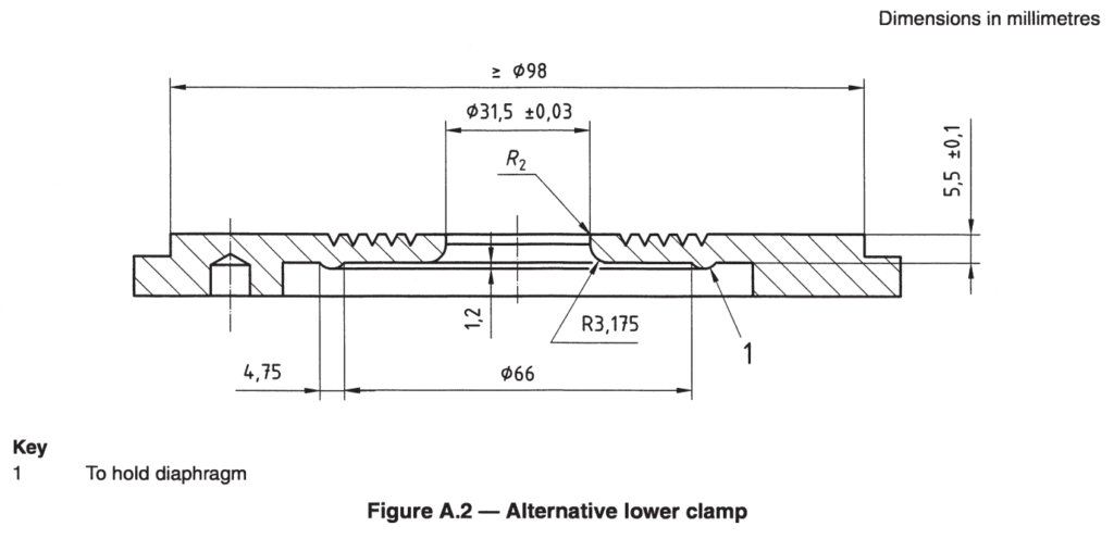
The dimensions of an alternative lower clamp are shown in Figure A.2. This clamp may sometimes be found Qn instruments of North American manufacture.
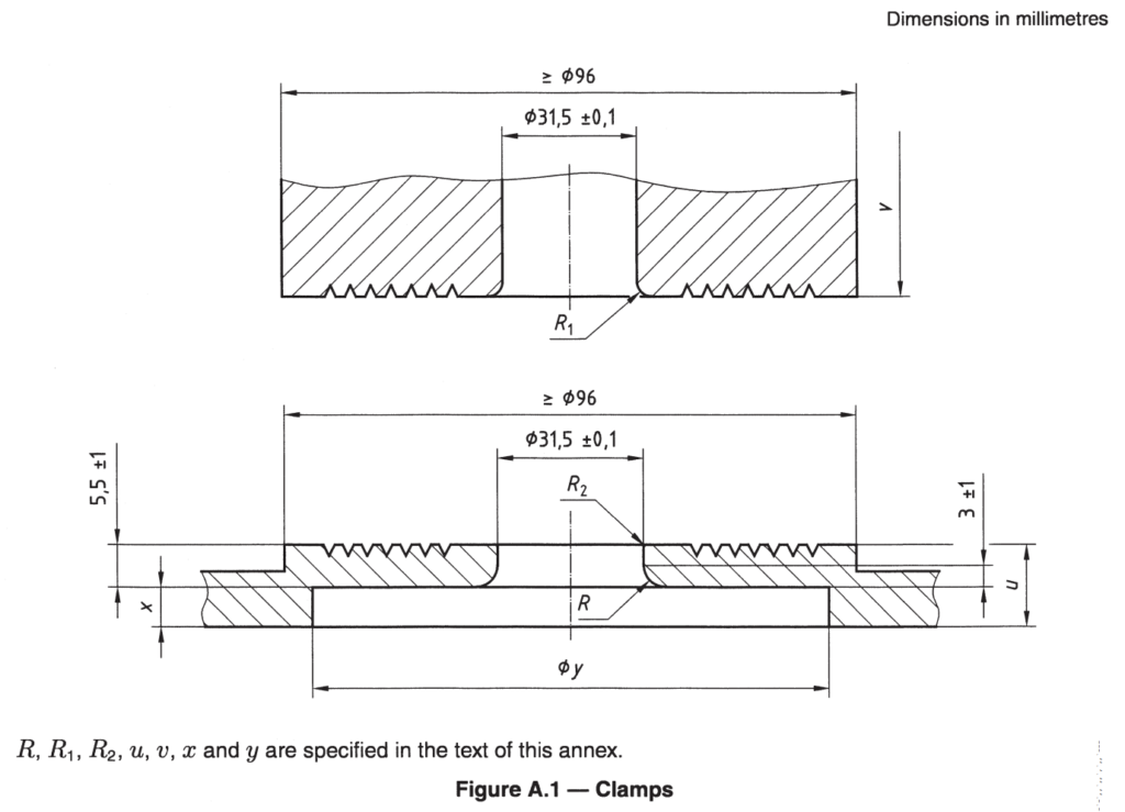
Dimensions ‘u and u (see Figure A.1) are not critical but shall be large enough to ensure that the clamps do not distort during use. For the moving clamp, a minimum thickness of 9,5 mm has been found satisfactory in use.
Dimensions :r and y may vary according to the manufacturer of the burst tester and the design of the diaphragm used but are such that the diaphragm is securely clamped.
Radius R, is set by the limits imposed by the dimensions 5,5 mm ± 1,0 mm and 3 mm ± 1 mm. The arc shall be tangential to the vertical face of the circular opening and to the horizontal inner surface of the diaphragm clamp. The radius shall be about 3 mm.
To reduce the danger of damage to the test piece or the diaphragm, R, and R2 shall be very slightly rounded but not sufficiently to affect the bore of the moving clamping plate. (Radii of curvature of about 0,6 mm for R1 and 0,4 mm for R2 are recommended.)
To minimize slippage, the clamp surfaces which come into contact with the board during a test shall have spiral or concentric tool marks on the surface.
The following have been found to be satisfactory:
a) a continuous spiral 60° V-groove not less than 0,25 mm deep, with a pitch of 0,9 mm 4- 0,1 mm, the groove starting at 3,2 mm i- 0,1 mm from the edge of the circular opening;
b) a series of concentric 60° V-grooves not less than 0,25 mm deep and 0,9 mm L 0,1 mm apart, the centre of the innermost groove being 3,2 mm ± 0,1 mm from the edge of the circular opening.
The space above the circular opening in the moving clamp shall be of sufficient size to allow free bulging of the test piece and, if enclosed as a design feature, shall be connected to the atmosphere by a circular opening of sufficient size to allow air trapped above the test piece to escape. A circular opening of about 4 mm diameter has been found to be suitable.
Edgewise crush resistance shall be tested as in DIN EN ISO 3037
5 Apparatus
5.1 Fixed-platen compression testing machine as described in ISO 13820. It is preferable to avoid
the use of emery paper on the platens.
While it is safer to avoid the use of emery paper on the platens, because it is a requirement of other test
methods, the platens may be faced with very fine emery paper of a grade not coarser than 00. Where this
is done, due regard should be paid to maintaining the flatness and parallelism requirements specified
for the faces.
NOTE A flexible beam compression tester per ISO 13820 is not recommended for this test method as there are significant questions regarding its ability to be maintained with sufficient parallelism to provide accuratetest values for these specimens.
5.2 Cutting device, such as a high-speed table saw or Billerud-type cutter (see Annex A), capable of
cutting test pieces to the quality of cut described in 8.3 and 8.4. 5.3 Guide blocks, two rectangular, smooth-finished, blocks of dimensions approximately 20 mm x 20 mm x 100 mm, to support the test piece and keep it perpendicular to the platen surfaces. It is advisable to fit each guide block with a probe, to enable each block to be moved safely during the test.
8 Preparation of test pieces
8.1 Prepare the test pieces in the same atmospheric conditions as used to condition the sample.
8.2 Using a sharp blade and a procedure that ensures the cuts are parallel, cut, from the sample,
specimens with the following dimensions: 100,0 mm ± 0,5 mm in the direction perpendicular to the
flutes and 70 mm to 300 mm in the direction parallel to the flutes, such that test pieces can be obtained
from an undamaged area of the sample.
8.3 From undamaged areas of the specimens (8.2), using an appropriate cutting device (5.2), cut
sufficient test pieces 25,0 mm ± 0,5 mm in the direction parallel to the flutes, so that 10 valid tests are
obtained. Each test piece will then measure 25,0 mm ± 0,5 mm in height (the direction of the flutes) and
100,0 mm ± 0,5 mm in length (the direction perpendicular to the flutes).
If a Billerud-type cutter (5.2) is used, insert the uncut strip until it almost contacts the end stop, and
ensure that a sufficient length of strip extends on the other side of the blades and that the edge is in
contact with the squareness guide.
Irrespective of the method of cutting, the edges subjected to load shall be cleanly cut, straight, parallel
and perpendicular to the board surfaces (8.4).
9 Procedure
Conduct the tests in the standard atmosphere that was used in Clause 7. With the platens of the compression tester (5.1) conveniently separated, place the test piece on one of its 100 mm cut edges onto the lower platen. Support it by placing a guide block (5.3) on each side. The guide blocks may be relocated away from the test piece when the load reaches about 50 N. They may be either left on the platen or removed from it. If applicable, take whatever action is appropriate to ensure that the weight of the guide blocks does not contribute to the force reading.
Operate the tester until the test piece fails. Test failure can be identified by a maximum in the loaddeflection curve, which often corresponds to visual compression in the body of the specimen and/or
curling of the edges of the specimen where they are in contact with the loading platens. Record, to the nearest 1 N, the maximum force, Fmax, developed up to the moment when instant failure occurs. Repeat the test on sufficient test pieces, so that at least 10 valid results are obtained.
10 Calculation
10.1 Calculate the mean maximum force, Fmax , and standard deviation, sFmax .
10.2 Calculate the edgewise crush resistance R, expressed in kilonewtons per metre, to the
nearest 0,01 kN/m using the equation:

10.3 Calculate the standard deviation of the edgewise crush resistance, sR, expressed in kilonewtons per
metre, to the nearest 0,01 kN/m, using the equation:

Annex A
(informative)
Examples of suitable cutting devices
A.1 High-speed table saw equipped with a small-tooth, no-set, hollow ground blade and minimum
clearance throatplate, and with the saw blade at 90° to the table supporting the sample.
A.2 Billerud-type cutter fitted with flat, straight, parallel and sharp blades approximately 0,5 mm thick, sharpened to a bevel of about 3 mm. If single-bevel blades are used, the blades should be mounted
so that the plane sides of the blades face each other, i.e. inwards. The blades of such a cutter must be kept in good alignment. A Billerud-type cutter is usually unsuitable for cutting test pieces from triple-wall
board and some heavyweight double-wall board. It is recommended that the blades of this type of cutter should not be used more than 50 times between sharpening or replacement.

- Cone size 60*60*60 mm
- capacity 1-48J (as per customer request)
- 7″ touch display
- Thermal printer included for report out
- Direct ready of result
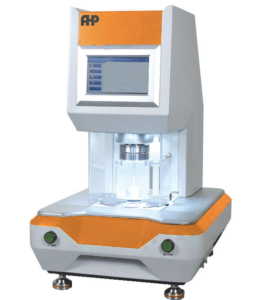
- Test area 50 cm2
- Hydraulic pressure increase
- Elastic diaphragm
- Touch display showing pressure and height of sample at burst
- USB data output to MS Excel
- Manual valve for flow adjustment of hydraulic system
- Pneumatic grip of sample
- Height indication of sample at bursting using linear transducer
- Pressure indication of sample piece
- Maximum pressure is 1000KPa
- Clamping pressure adjustment of sample piece
- Burst pressure indication
- Training video included

