4 Principle
A test specimen of rectangular cross-section, resting on two supports, is deflected by means of a loading edge acting on the specimen midway between the supports. The test specimen is deflected in this way at a constant rate at midspan until rupture occurs at the outer surface of the specimen or until a maximum strain of
5 % (see 3.8) is reached, whichever occurs first. During this procedure, the force applied to the specimen and the resulting deflection of the specimen at midspan are measured.
5Test machine
5.1General
Themachine shall comply with ISO 7500-1 and ISO 9513 and the requirements given in 5.2 to 5.4.
5.2Test speed
The test machine shall be capable of maintaining the test speed (see 3.1), as specified in Table 1.

5.3 Supports and loading edge
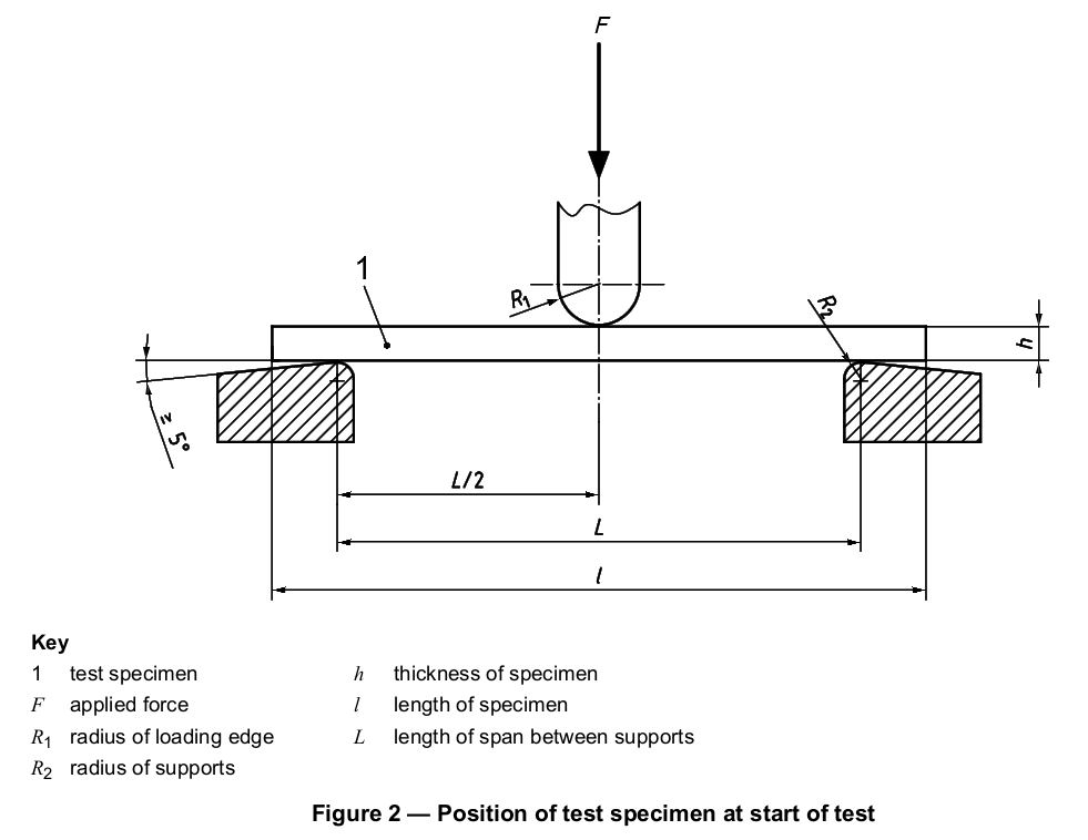
Two supports and a central loading edge shall be arranged as shown in Figure 2. The supports and the loading edge shall be parallel to within ±0,2 mm over the width of the test specimen.
The radius, R1, of the loading edge and the radius, R2, of the supports shall be as follows:
R1 = 5,0 mm ± 0,2 mm;
R2 = 2,0 mm ± 0,2 mm for test specimen thicknesses u 3 mm;
R2 = 5,0 mm ± 0,2 mm for test specimen thicknesses > 3 mm.
The span, L, shall be adjustable.
5.4 Force- and deflection-measuring systems
5.4.1 Force-measuring system
The force-measuring system shall comply with the requirements of class 1 as defined in ISO 7500-1.
5.4.2 Deflection-measuring system
The deflection-measuring system shall comply with the requirements of class 1 as defined in ISO 9513. This shall be valid over the whole range of deflections to be measured. Non-contact systems may be used provided they meet the accuracy requirements stated above. The measurement system shall not be influenced by machine compliance.
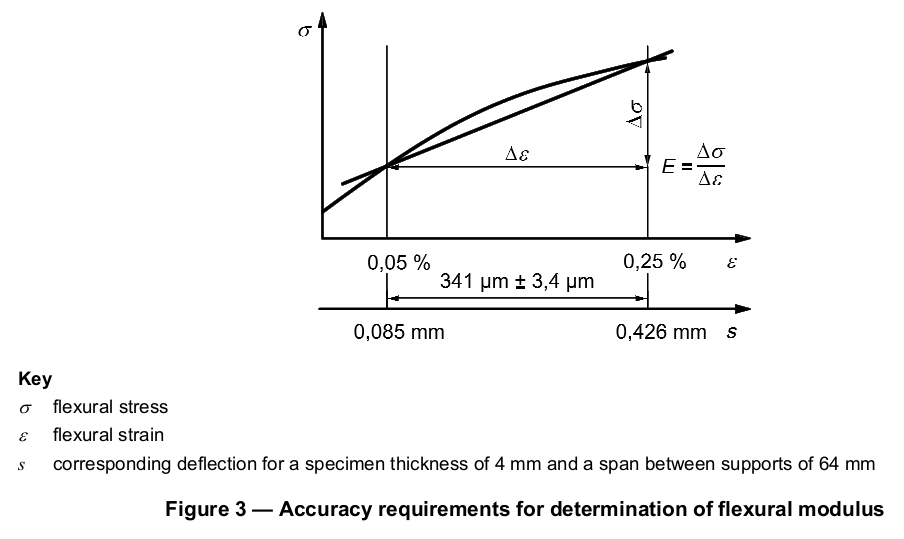
When determining the flexural modulus, the deflection-measuring system shall be capable of measuring the change in deflection to an accuracy of 1 % of the relevant value or better, corresponding to ±3,4 µm for a support span, L, of 64 mm and a specimen thickness, h, of 4,0 mm (see Figure 3). Other support spans and specimen thicknesses will lead to different requirements for the accuracy of the deflection-measuring system.
Any deflection indicator capable of measuring deflection to the accuracy specified above is suitable.
NOTE The crosshead displacement includes not only the specimen deflection but also the indentation of the loading edge and the supports into the specimen and deformation of the machine. The last of these is machine-dependent as well as load-dependent. Results determined on different types of machine are therefore not comparable.
In general, measurement of crosshead displacement is not suitable for modulus determination unless a compliance correction is applied.
6 Test specimens
6.1 Shape and dimensions
6.1.1 General
The dimensions of the test specimens shall comply with the relevant material standard and, as applicable, with 6.1.2 or 6.1.3. Otherwise, the type of specimen shall be agreed between the interested parties.
6.1.2 Preferred specimen type
The dimensions, in millimetres, of the preferred test specimen are:
length, l: 80 ± 2
width, b: 10,0 ± 0,2
thickness, h: 4,0 ± 0,2
In any one test specimen, the thickness within the central third of the length shall not deviate by more than
2 % from its mean value. The width shall not deviate from its mean value within this part of the specimen by more than 3 %. The specimen cross section should preferably be rectangular, with no rounded edges, except as noted in 6.4.
The preferred specimen may be machined from the central part of a multipurpose test specimen complying with ISO 20753.
6.1.3 Other test specimens
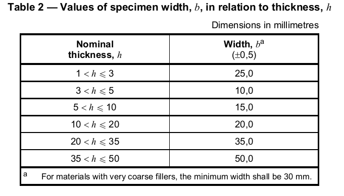
When it is not possible or desirable to use the preferred test specimen, use a specimen with the dimensions given in Table 2.
NOTE Certain specifications require that test specimens from sheets of thickness greater than a specified upper limit be reduced to a standard thickness by machining one face only. In such cases, it is conventional practice to place the test specimen such that the original surface of the specimen is in contact with the two supports and the force is applied by the central loading edge to the machined surface of the specimen.