4 Test apparatus
The test apparatus shall consist of the test chamber, standard ladder and ignition source, as described in
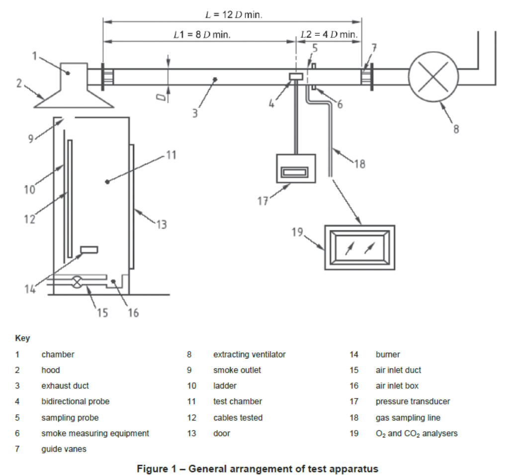
EN 60332-3-10, with the additional features as specified in 4.2 to 4.8. Figure 1 shows a schematic
diagram of the apparatus. The ignition source shall be one ribbon-type propane gas burner. The ladder
shall be the standard ladder of (500 ± 5) mm width. The air supply shall be a system that blows air into the chamber at an airflow rate of (8 000 ± 400) l/min.
The additional features of the apparatus shall be capable of measuring the following parameters:
a) oxygen consumption;
b) CO2 production;
c) volume flow in the exhaust duct;
d) smoke production.
WARNING Care should be taken in monitoring and extinguishing cable fires once the test specimen has
started to propagate fire. Some specimens may have a very high capacity to generate high heat release
levels that could damage the test equipment and instrumentation. It is important that testing staff are
sufficiently trained in dealing with such fires and have adequate fire fighting facilities at their disposal
during testing.
NOTE 1 It is recommended that indicative temperature measurements are taken through the use of thermocouples installed along the cable bunch being tested at 1,5 m and 2,5 m above the burner and at the top of the chamber or in the duct. Such measurements can give an early indication of any excessive temperature or burning condition that may require the test to be aborted in order to prevent damage to the test equipment.
All data shall be measured and recorded every 3 s. These point measurements shall be averaged over a
period of 30 s for parameters relating to heat release and 60 s for parameters relating to smoke
production, in order to provide the required data. The data shall be processed according to the
requirements of this standard.
The additional features and their associated measurements shall allow for calculation of the following:
a) heat release (see Annex A);
1) heat release rate (HRR);
2) total heat release (THR);
3) fire growth rate index (FIGRA);
b) smoke production (see Annex B);
1) smoke production rate (SPR);
2) total smoke production (TSP).
4.2 Air input
Air shall be introduced to the test chamber through a plenum box fitted directly underneath, and of
approximately the same dimensions as, the air inlet aperture. The depth of the plenum box shall be
(150 ± 10) mm. Air shall be blown into the plenum box from a fan through a rectangular straight section of duct of constant cross section of (300 ± 10) mm width and (80 ± 5) mm height and a minimum length of 800 mm, which shall enter from the rear of the chamber and be parallel to the floor and along the burner centre line as shown in Figure 1. The duct shall be arranged to inlet air to the plenum box through an aperture in the longest side, centred horizontally and such that the bottom of the duct shall be no greater than 10 mm above the bottom of the plenum box. A grid shall be fitted in the air inlet aperture to achieve uniform flow of the air. The grid shall be constructed of steel plate approximately 2 mm thick with holes of approximately 5 mm diameter drilled at approximately 8 mm spacing between centres.
The airflow rate shall be measured in a circular duct prior to the rectangular cross section duct. It shall be
measured by a gas flow measuring device located at a straight section of the circular duct. The minimum
length of straight circular section before and after the measuring device shall be selected according to the
technical specification of the measuring device.
NOTE 1 A fluid flow measuring system according to either EN ISO 5167-2 (orifice plate) or EN ISO 5167-4 (Venturi tube) is recommended. Alternatively, a Pitot tube taking multiple samples across the section of the duct and averaging to account for variations across the section or a hot wire anemometer measuring at multiple positions across the section of the duct as described in Annex D may be used.
The airflow shall be set prior to a test at (8 000 ± 400) l / min and shall not be changed during the test. The airflow shall be checked throughout the test and shall not vary by more than 10 % of the set value.
NOTE 2 This information does not need to be recorded.
4.3 Hood
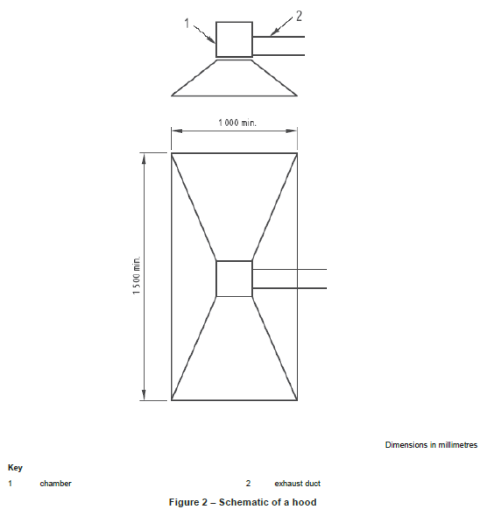
A hood (see Figure 2) having a truncated shape, and where the base has a minimum length of 1,50 m and
a minimum width of 1,00 m, shall be centred above the outlet of the test chamber. The base of the hood
shall be raised above the top of the test chamber, with the largest side of the hood parallel to the largest
side of the outlet of the chamber.
NOTE 1 A gap of approximately 200 mm to 400 mm between the top of the test chamber and the base of the hood has generally been found suitable.
There shall be a chamber above the hood to allow a connection to the exhaust duct.
NOTE 2 Plates/baffles may be installed in the hood to improve mixing of the air / effluents.
The system shall be designed to collect all the combustion products leaving the test chamber through the
outlet during the test. There shall be no leakage of flames or smoke. The exhaust capacity shall be at
least 1 m³/s at normal pressure and a temperature of 25 °C. The exhaust system design shall not be
based on natural convection.
NOTE 3 In order to extract all gases and vapours, especially in the case of heavily burning cables, or cables which require to be specially extinguished and produce high volumes of gases and vapours, an exhaust system with a capacity of 1,5 m³/s is recommended.
4.4 Exhaust duct
An exhaust duct shall be connected to the hood as described in 4.3. The inner diameter, D, of the duct
shall be in the range 250 mm to 400 mm. The straight section of the duct shall have a minimum length of
12 x D, such that a uniform flow profile is established at the point of measurement.
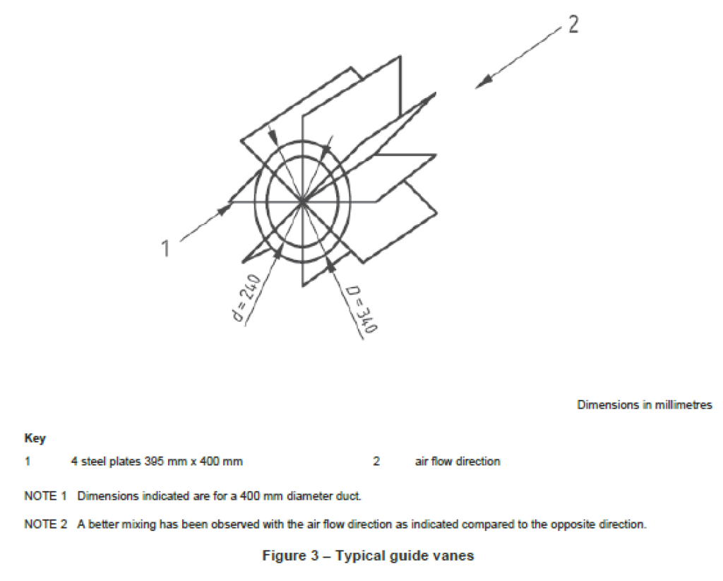
NOTE A uniform flow profile can be obtained by introducing guide vanes (see Figure 3) before and after the measuring section such as described in EN 14390. This is highly recommended in order to obtain as precise measurements as possible.
4.5 Instrumentation in the exhaust duct
4.5.1 Volume flow
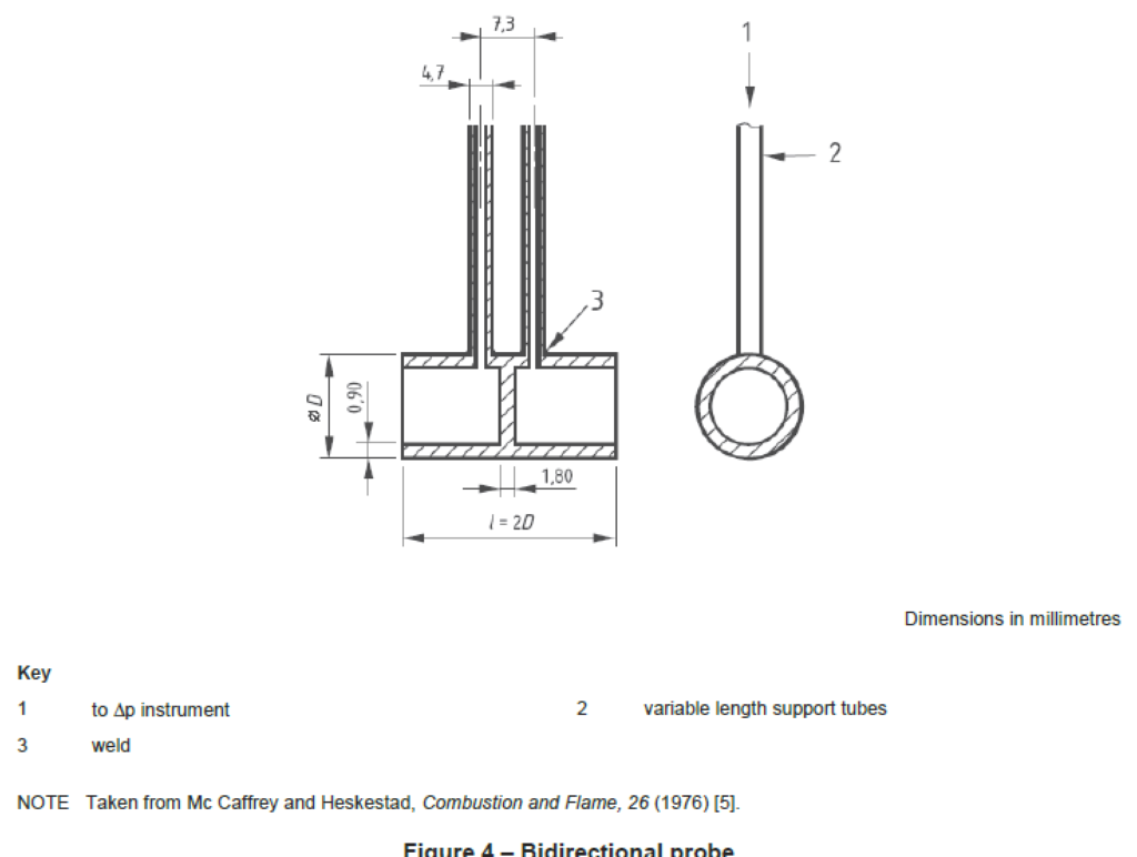
The flow shall be measured by a bidirectional probe located at the centre line of the duct and at a
minimum distance from the beginning of the straight section of exhaust duct of 8 x D. The length of the
straight section of duct beyond the probe shall be at least 4 x D. The probe which is shown in Figure 4
consists of a stainless steel cylinder, 32 mm long and with an outer diameter of 16 mm. The cylinder is divided into two equal chambers. The pressure difference between the two chambers shall be measured by a pressure transducer. The plot of the probe response versus the Reynolds number is shown in Figure 5 (see also Annex C).
The pressure transducer shall have a measuring precision better than ± 5 Pa. A suitable range of
measurement is 0 Pa to 200 Pa (when using duct diameters between 250 mm and 400 mm).
The two connection pipes between the bidirectional probe and the pressure transducer shall be of the
same length.
Gas temperature in the immediate vicinity of the probe shall be measured by a sheathed K type
thermocouple with a maximum diameter of 1,5 mm in accordance with EN 60584-1. The thermocouple
shall be positioned so that it does not disturb the flow pattern around the bidirectional probe.
NOTE If more than one thermocouple is used then all thermocouples shall be of the same size and type.
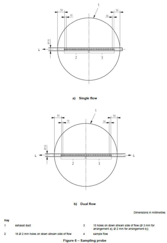
4.5.2 Sampling probe
The sampling probe shall be located where the exhaust duct flow is well mixed. The probe shall have a
cylindrical form so that disturbance of flow is minimised. The gas samples shall be taken along the whole
diameter of the exhaust duct. Examples of suitable sampling probes are shown in Figure 6. The intake of
the sampling probe shall be turned downstream in order to avoid soot clogging in the probe. The sampling probe shall be connected to the gas analysers for oxygen (O2) and carbon dioxide (CO2) by a suitable sampling line.
4.5.3 Sampling line
The sampling line shall be manufactured from corrosion resistant material, e.g. PTFE. The combustion
gases shall be filtered with inert filters to the degree of particle concentration required by the gas analysis
equipment. The filtering procedure shall be carried out in more than one step. The system shall be
capable of removing water vapour.
The combustion gas shall be transported by a pump which does not emit oil, grease or similar products,
as these may contaminate the gas mixture.
NOTE A membrane pump is suitable.
A pump capacity between 10 l/min and 50 l/min is recommended. The pump shall generate a pressure
differential of at least 10 kPa to reduce the risk of clogging of the filters by smoke.
The sampling line (see Figure 7) shall be connected at its end to O2 and CO2 analysers.
4.6 Extracting ventilator
At the end of the exhaust duct, an extracting ventilator shall be installed. A minimum exhaust capacity of
1,5 m³/s at normal pressure and at a temperature of 25 °C is recommended.
NOTE Legal requirements may make it necessary for equipment for collecting and washing the effluent to be fitted to the test chamber. This equipment shall be such as to collect all the effluents without causing a change in the air flow rate through the test chamber.
4.7 Smoke production measuring equipment
4.7.1 General
The optical density of the smoke can be measured by two different measuring techniques as described in
4.7.2 and 4.7.3. Although the measurement principle differs for both systems, it has been shown that the
two different systems do not give substantially different results [3].
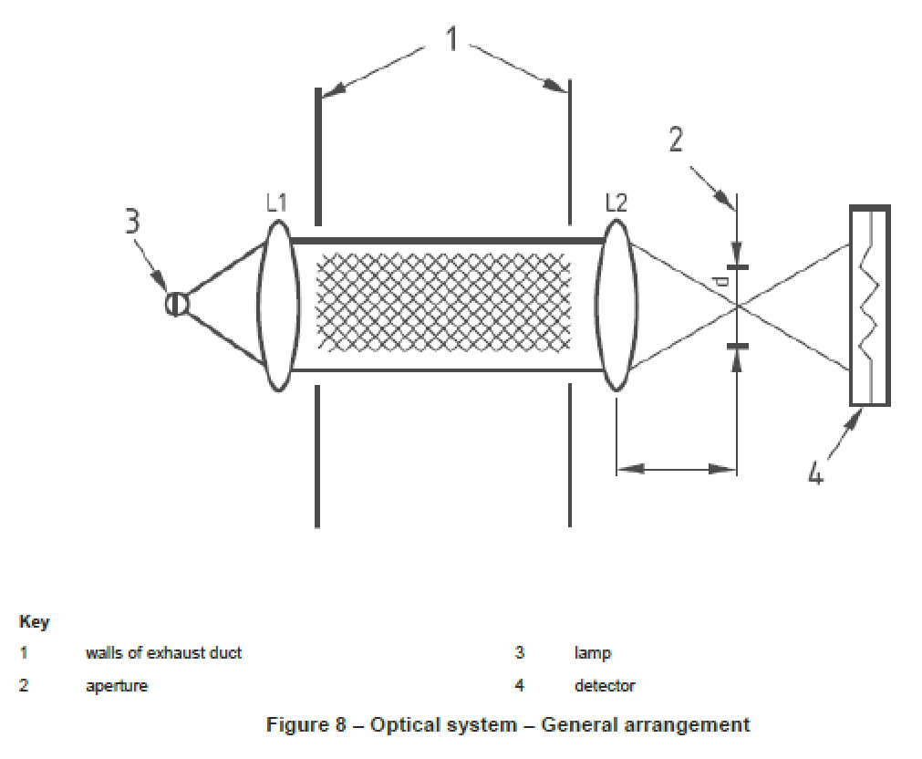
A general arrangement of an optical system is shown in Figure 8.
NOTE 1 Other systems may be used provided that their equivalence to those specified has been demonstrated.
NOTE 2 Based upon experience, white light systems are recommended.
The smoke production measuring equipment shall be located where the exhaust duct flow is well mixed.
4.7.2 White light system
A light attenuation system, of the white light type, mounted with a flexible connection to the side ducts of
the exhaust duct, shall consist of the following.
a) A lamp, of the incandescent filament type operating at a colour temperature of (2 900 ± 100) K.
The lamp shall be supplied with stabilized direct current, stable within 0,5 % (including temperature,
short-term and long-term stability).
b) A lens system, to align the light to a parallel beam and with a diameter of at least 20 mm.
The photocell aperture shall be placed at the focus of the lens in front of it and it shall have a
diameter, d, chosen with regard to the focal length of the lens, f, so that d/f is less than 0,04.
c) A detector, with a spectrally distributed responsivity agreeing with the CIE V(λ) function (CIE photopic
curves) to an accuracy of within ± 5 %. The detector output shall, over an output range of at least two decades, be linear within 3 % of the measured transmission value or 1 % of the absolute transmission.
Calibration of the light attenuation system shall be carried out according to E.4. The 90 % response time
of the system shall be not more than 3 s.
Air may be introduced in the side ducts so that the optics stay clean, within the given light attenuation drift requirements (see E.4.2). Pressurized air can be used instead of a self suction system.
4.7.3 Laser light system
A laser photometer system shall use a helium-neon laser with a power output between 0,5 mW and 2,0 mW.
Air may be introduced in the side ducts so that the optics stay clean, within the given light attenuation drift requirements (see E.4.2). Pressurized air may be used instead of a self suction system.
NOTE The optics should be regularly inspected and cleaned from smoke deposition whenever necessary.
4.8 Combustion gas analysis equipment
4.8.1 General
The analysis of oxygen, and carbon dioxide, requires that any water vapour in the combustion gases shall
be trapped by means of a suitable drying agent.
4.8.2 Oxygen
The analyser shall be of the paramagnetic type and capable of measuring a range of 16 % to 21 %
oxygen (VO2 /Vair). The noise and drift of the analyser shall be not more than 0,01 % (100 parts per million) over a period of 30 min as measured in accordance with E.2.3. The manufacturer’s declared response time of the analyser shall be not more than 12 s. The output from the analyser to the data acquisition system shall have a resolution better than 0,01 % (100 parts per million).
4.8.3 Carbon dioxide
Continuous analysis of carbon dioxide shall be achieved using an IR spectrometer. The analyser shall be capable of measuring a maximum range of 0 % to 10 % carbon dioxide. The linearity of the analyser shall be 1 % of full scale or better and the manufacturer’s declared response time shall be not more than 12 s.