
4 Principle
The test mixture, consisting of a color concentrate and a basic test polymer, is passed through an extruder fitted with melt pump and screen pack with breaker plate. In front of the screen pack is a melt pressure transducer. The pressure difference between the start pressure and the maximum pressure is used to calculate the filter pressure value [FPV].
6 Apparatus
6.1 General
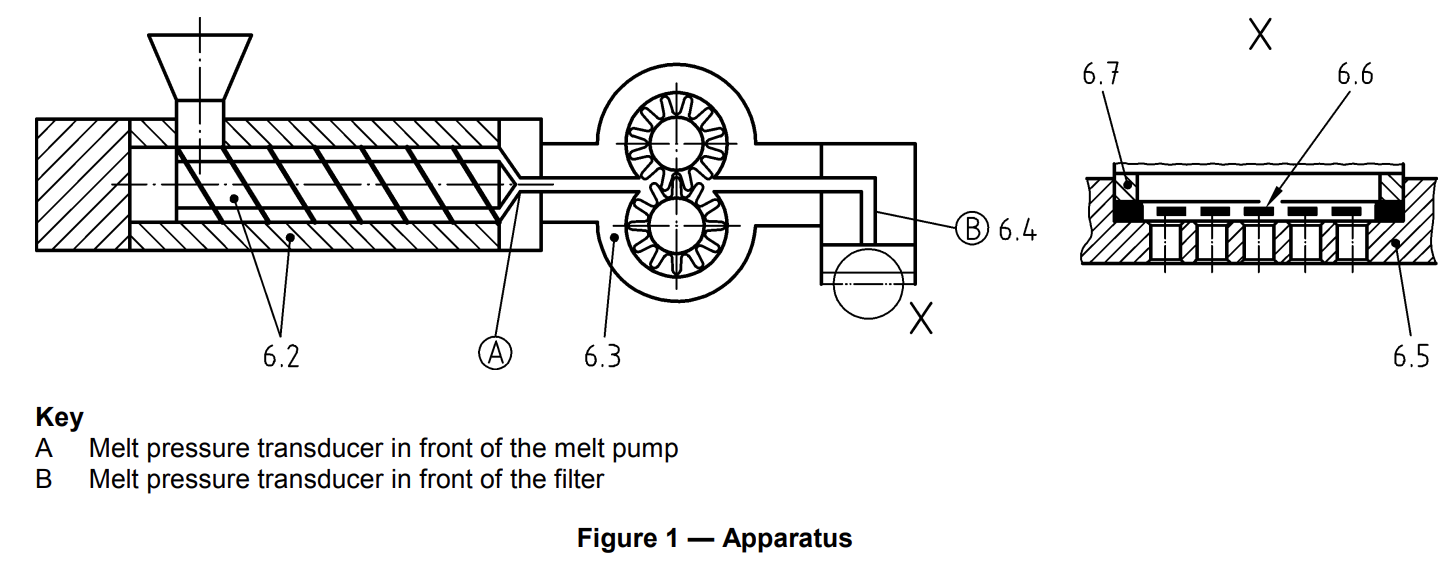
Figure 1 illustrates the principle construction of the apparatus (see 6.2 to 6.7).
6.2 Extruder
A single screw extruder with non-grooved barrel and a screw without dispersing elements shall be used. A screw with a diameter between 19 mm and 30 mm and with a length of 20 L/D to 30 L/D (length/diameter) is recommended. It is necessary to have a melt pressure transducer in front of the melt pump (A) to measure the pressure of the melt. An electronic controller with screw speed/pressure feedback loop is necessary in order to maintain this pressure constant, preferably at a level between 30 bar and 60 bar, to ensure that the melt pump is completely filled and to ensure optimum homogeneity of the melt.
6.3 Melt pump
The melt pump, preferably a metering pump, shall provide a constant throughput of 50 cm³/min to 60 cm³/min.
6.4 Melt pressure transducer
The pressure range shall be preferably between 0 bar and 100 bar for mixture 1 (7.2) and between 0 bar and 350 bar for mixture 2 (7.3). The accuracy of the melt pressure transducer (B) shall be within ± 1% with a repeatability of less than ± 0,1%.
NOTE The resolution of the pressure measurement should be 0,1 bar.
6.5 Breaker plate
A breaker plate is used to support the screen-pack and defines its free area (see Annex A).
6.6 Filter
6.6.1 General
The filter media is that part of the system which influences the differential pressure used as the basic data for determining the results of the test.
The differential pressure increase is dependent on the retention characteristics of the filter media.
In order to have comparable results it is important that the filter media is defined in detail and assembled exactly to specification.
Screen-packs are used as filter media. The screen-pack is assembled from ultrasonically cleaned filter discs, having a filter diameter of 33,8 mm (± 0,1 mm), in a multi-layer construction, preferably held together in an aluminium frame. All screens shall be made from a suitable material appropriate to the polymer used, e.g. stainless steel in accordance with EN 10088-1, Type 1.4404. Any change in specification (e. g. weaving pattern, surface condition, number of apertures per unit length or aperture width) can lead to a different test result.
6.6.2 Screen-pack 1
Two-layer construction, where the first layer is a reverse plain dutch weave 615/108 warp/weft per 25,4 mm with a wire diameter of 0,042 mm/0,14 mm and the second layer (support mesh) is a square mesh plain weave 0,63 mm aperture width with a wire diameter of 0,40 mm calendered (for further details see ISO 9044).
6.6.3 Screen-pack 2
Two-layer construction, where the first layer is a reverse plain dutch weave 615/132 warp/weft per 25,4 mm with a wire diameter of 0,042 mm/0,13 mm and the second layer (support mesh) is a square mesh plain weave 0,63 mm aperture width with a wire diameter of 0,40 mm calendered (for further details see ISO 9044).
6.6.4 Screen-pack 3
Three-layer construction, where the first layer is a twilled dutch weave 165/1400 warp/weft per 25,4 mm with a wire diameter of 0,071 mm/0,040 mm and the second layer (support mesh) is a square mesh plain weave 0,25 mm aperture width with a wire diameter of 0,16 mm and the third layer (support mesh) is a square mesh plain weave 0,63 mm aperture width with a wire diameter of 0,40 mm calendered (for further details see ISO 9044).
NOTE 1 The use of further finer screen-packs than described in 6.6.2 may be agreed between the interested parties.
NOTE 2 It is recommended to request confirmation from the supplier that the above specifications are used for the screenpack. Especially the number of apertures per unit length and the wire diameters of the individual layers are extremely critical for the result of the filter pressure value test.
6.7 Sealing ring
The sealing ring or aluminium frame of the filter disc should have a diameter of 33,8 mm ± 0,1 mm and an inside diameter of 28 mm ± 0,1 mm.
If the screen-pack has no aluminium frame a sealing ring is to be used.
7 Preparation of test mixtures
7.1 General
The colour concentrate (5.1) and the basic test polymer (5.2) are mixed together, for example in a glass or plastics container, to provide the homogeneous test mixture.
NOTE 1 Mixture 1 is recommended for colour pigments and mixture 2 is recommended for white and carbon black pigments.
NOTE 2 The use of other mixtures may be agreed between the interested parties.
NOTE 3 Colorant quantities below 5,0 g will lead to insufficient accuracy.
7.2 Mixture 1
A test mixture of 200 g (100 %), including 5,0 g colorant (2,5 %) is used.
NOTE If the colour concentrate contains 40% colorant the quantities are: 12,5 g colour concentrate and 187,5 g basic test polymer.
7.3 Mixture 2
A test mixture of 1000 g (100 %), including 80,0 g colorant (8 %) is used.
NOTE If the colour concentrate contains 40% colorant the quantities are: 200 g colour concentrate and 800 g basic test polymer.
8 Procedure
8.1 Pre-conditioning
The complete apparatus (Clause 6) should be pre-heated to the processing temperature appropriate for the basic test polymer.
The equipment should be cleaned or adequately purged with the basic test polymer (5.2) before each test is started.
8.2 Determination
Mount a new screen-pack (6.6.2 to 6.6.4) in front of the breaker plate (6.5) and the measuring equipment in such a way that the melt flows through the finer screen first and through the breaker plate last. A sealing ring (6.7) shall prevent leakage of the mixture around the edge of the screen-pack.
Allow sufficient time for the screen-pack and the breaker plate to reach the temperature of the equipment. This time will depend on the equipment being used. The basic test polymer (5.2) is then plasticized in the extruder and passed through the screen-pack with a defined melt volume throughput until the melt temperature and pressure remain constant. The machine conditions should guarantee a constant melt temperature, with temperature deviations of less than ± 2°C.
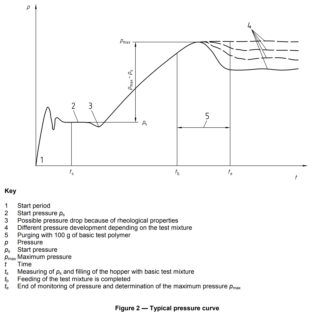
Measure the start pressure ps developed by the basic test polymer directly in front of the screen-pack. The start pressure ps should be constant. When the hopper is empty and the extruder screw is just visible, add the test mixture (5.3).
NOTE A pressure drop can occur because of different rheological properties of basic test polymer and test mixture.
After feeding of the test mixture is completed, 100 g basic test polymer are added just as the extruder screw becomes visible again.
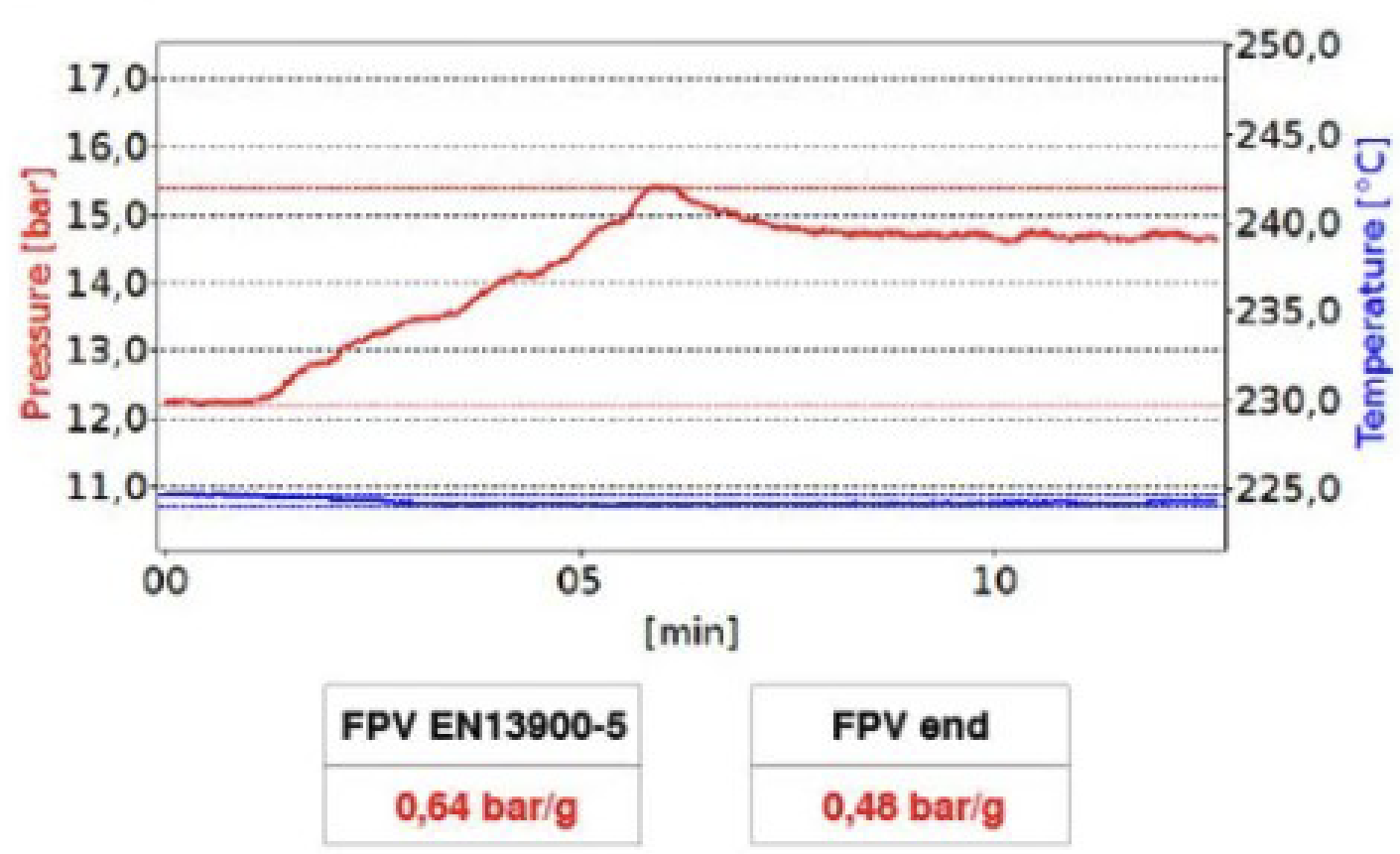
The test is finished as soon as the extruder screw once again becomes visible. Use the recorded data to evaluate the maximum pressure pmax and to calculate the filter pressure value.
Remove the screen-pack while still hot and purge the apparatus thoroughly with basic test polymer for the next test.
9 Evaluation
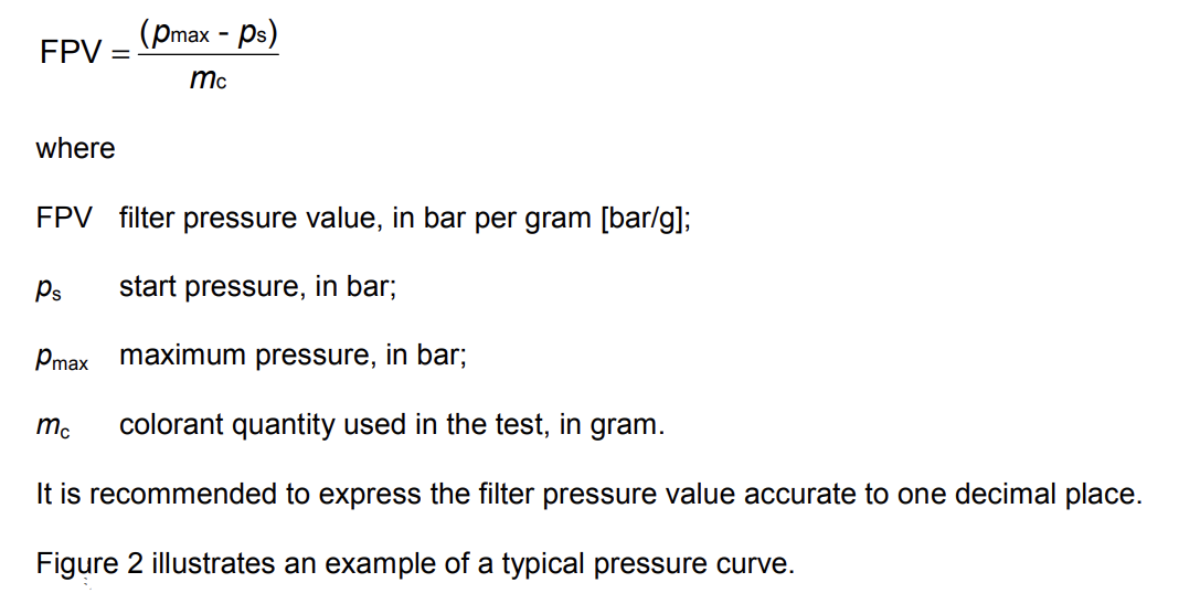
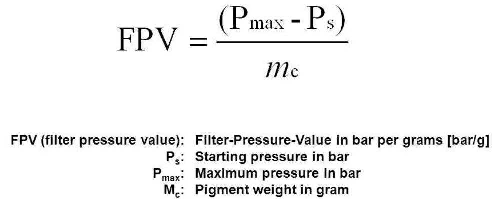
The filter pressure value [FPV], defined as the increase of pressure per gram colorant, is calculated by using the following equation:
10 Test report
The test report shall contain at least the following information:
a) reference to this European Standard (EN 13900-5);
b) all necessary details to identify the color concentrate tested;
c) all necessary details to identify the basic test polymer;
d) description of the test mixture (Clause 7);
e) all necessary details about the test procedure and the test conditions (e. g. test equipment, type of screen pack, melt temperature, melt volume throughput);
f) result of the test, as indicated in Clause 9;
g) any deviation from the test method specified;
h) date of the test.
Filter Pressure Value (FPV) Testing and its Role in Masterbatch Manufacturing
Masterbatches can be described as essential components in the vibrant world of plastics manufacturing, that serve as concentrated formulations (pigment and/or additive concentrates) and perform the crucial function of imparting color, enhancing properties, and introducing functionalities to a wide array of plastic products. These formulations, comprising pigments, additives, or other modifiers, are pivotal in transforming raw polymers into a diverse range of end-use plastics. The meticulous control of masterbatch quality is paramount in ensuring the consistent and desired characteristics of the final plastic products. One crucial aspect of quality control in masterbatch production involves Filter Pressure Value (FPV) testing—an important process that scrutinizes the manufacturing process’s stability, integrity, and efficiency. In this context, understanding the role of filter pressure testing is fundamental to guarantee the reliability and performance of masterbatches throughout the intricate journey from production to the end product.
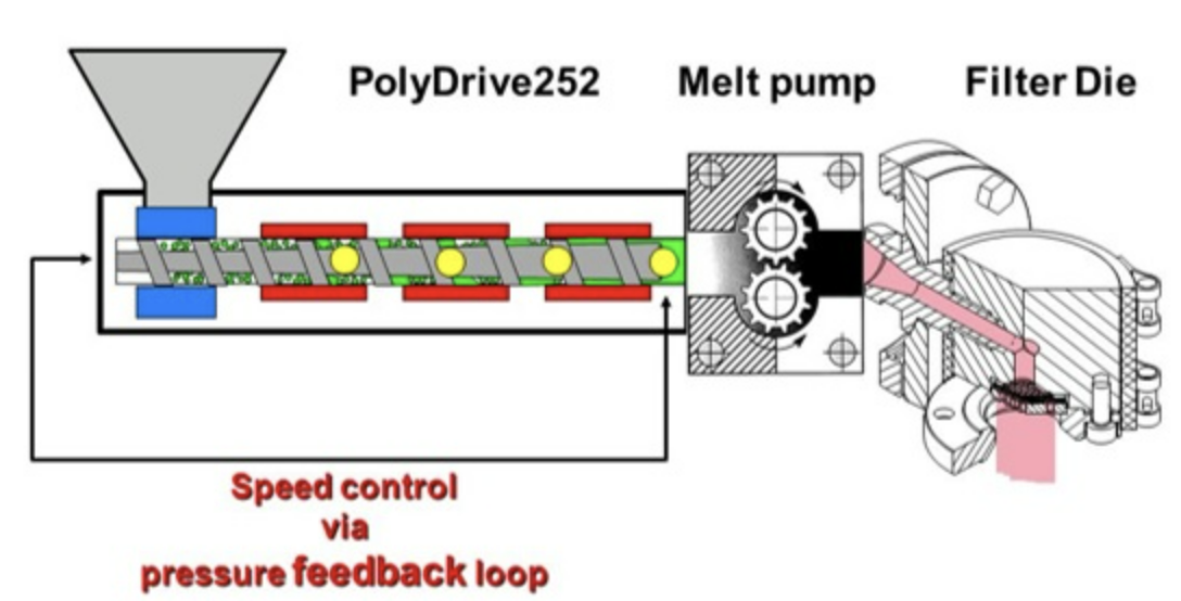
EN 13900-5 standard specifies the required equipment, including the extruder, melt pump, sieves, and breaker plate along with delineating the composition of the mixture, the testing protocol, and the evaluation criteria. FPV is introduced to gauge the quality and dispersion of pigments. Through standardized quality control measures, improvements in product quality become achievable. Furthermore, comparing FPV results facilitates the ranking of similar products from different vendors. Employing the FPV test for raw material assessments ensures product quality, while also enhancing the predictability of screen changer uptime. In terms of application and operation, it is suited for testing colorants presented as color concentrates in all polymers utilized for extrusion in melt-spinning processes. The testing mixture undergoes processing in a single screw extruder featuring a non-grooved barrel and a compression screw without additional mixing elements. The polymer melt is consistently delivered with a pressure range of 30 to 60 bar (435 to 870 psi) to the melt pump, maintaining a volume of 50 to 60 cm³/min (setting 660 on the Melt pump). As the polymer passes through the filter package, particles and agglomerates above a specific size are retained, causing a pressure increase that correlates with the colorant’s quality. The pressure difference between the initial and peak pressures is then employed in calculating the FPV, providing a comprehensive measure of filter performance.
The polymer melt is ensured to flow through the finer screen first to prepare for the test. An aluminum rim of the screen pack serves as a seal to prevent undermining. Next, the breaker plate and screen pack are heated and the machine is purged with basic test polymer to expedite temperature equalization while maintaining a stable melt temperature within ±2°C. The basic test polymer is plasticized in the extruder, pumping it through the screen pack until melt temperature and pressure stabilizes. The melt pump feeding pressure should be 30 to 60 bar (435 to 870 psi), with a volume flow of 50 to 60 cm³/min. The equipment must be maintained at a constant melt temperature with deviations less than ±2°C. The pressure (Ps) developed by the basic test polymer just in front of the screen pack is measured for a constant value. When the hopper is empty, and the feed-screw is visible, the test mixture is introduced. A pressure drop due to differing rheological properties can be expected. With the hopper empty and the feed screw visible, refilling is done with the basic test polymer. The test is concluded after 100 g of basic test polymer passes through the screen pack and pressure stabilizes.
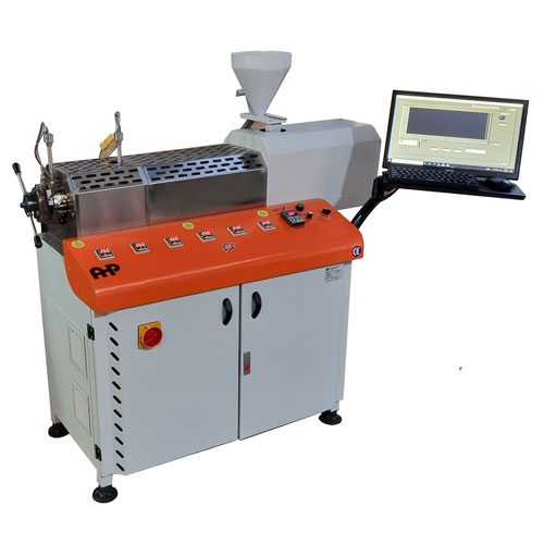
Filter Pressure Tester
- The melt pump is driven by servo motor
- Equipped with manual plate nitride treated screen changer of high hardness and wear resistance
- High precise melt pressure sensor provides an accurate melt pressure
- Computer included and machine has 6 ceramic heating zones
- Eqquipped with 2 melt pressure sensor and swiss made melt pump
- Software is based on LABVIEW and reporting is on MS WORD
- Pressure and melting temperature measurement
- Simple sieve change
- Data recording and evaluation using AHP Filter Test Software
- Fulfilment of DIN EN 13900-5
- Screw diameter: 25 mm
- Gear pump servo motor power: 0.75 KW
- Pressure range: Maximum 300 bar
- Gear pump inlet pressure: 0-100 bar
- Screw rotational speed: 0-100 rpm
- Filter 5-40 Micron