
4 Principle
4.1 Apparatus
Both the guarded hot plate apparatus and the heat flow meter apparatus are intended to establish within homogeneous specimens with flat parallel faces, in the form of slabs, a unidirectional constant and uniform density of heat flow rate. The part of the apparatus where this takes place with acceptable accuracy is around its centre; the apparatus is therefore divided into a central metering section in which measurements are taken, and a surrounding guard section.
4.2 Measuring the density of heat flow rate
With the establishment of steady state in the metering section, the density of heat flow rate, q, is determined from measurement of the heat flow rate, “phi”, and the metering area, A, that the heat flow rate crosses.
4.3 Measuring the temperature difference
The temperature difference across the specimens, Delta(T), is measured by temperature sensors fixed at
the surfaces of the apparatus in contact with the specimen and/or those of the specimens themselves,
where appropriate.
4.4 Deriving the thermal resistance or transfer factor
The thermal resistance, R, is calculated from a knowledge of q, A and Delta(T) if the appropriate
conditions given in A.3.2 are realized. From the additional knowledge of the thickness, d, of the
specimen, the transfer factor, T, is computed.
5.2 Guarded hot plate apparatus
5.2.1 General
In a guarded hot plate apparatus the heat flow rate is obtained from the measurement of the power input to the heating unit in the metering section. The general features of the apparatus with specimens installed are shown in Figure 1.
There exist two types of guarded hot plate apparatus, which conform to the basic principle outlined in clause 4:
a) with two specimens (and a central heating unit);
b) with a single specimen.
5.2.2 Two specimen apparatus
In the two specimen apparatus [see Figure 1a)], a central round or square flat plate assembly, consisting of a heater and metal surface plates, called the heating unit, is sandwiched between two nearly identical specimens. The heat flow rate is transferred through the specimens to separate round or square isothermal flat assemblies, called the cooling units.
5.2.3 Single specimen apparatus
In the single specimen apparatus [see Figure 1b)], one of the specimens is replaced by a combination of a piece of insulation and a guard plate. A zero temperature-difference is then established across this combination. Providing all other applicable requirements of this standard are fulfilled, accurate measurements and reporting according to this method may be accomplished with this type of apparatus, but particular reference to the modification of the normal hot plate with two specimens should be made in the test report.
5.2.4 Heating unit
The heating unit consists of a separate central metering section, where the unidirectional constant and uniform density of heat flow rate can be established, surrounded by a guard section separated by a narrow gap.
5.2.5 Metering area
The metering area is the central area of the specimen delimited by the centre line of the gap of the heating unit.
This definition, which applies in principle to thick specimens only, has been retained for all the specimens to be tested according to this standard: due to this approximation, the thickness of the specimen shall be at least ten times the width of the gap.
5.2.6 Edge insulation and auxiliary guards
Additional edge insulation and/or auxiliary guard sections are required especially when operating above or below room temperature, see annex B of EN 1946-2:1999.
5.2.7 Cooling units
The cooling units shall have dimensions at least as large as those of the heating unit, including the guard heater(s). They shall consist of metal plates maintained at a constant and uniform temperature.
6 Test specimens
6.1 General
Testing may be split into specimen handling, see below, and actual measurements, see clause 7.
Some decisions about measurable heat transfer properties, specimen handling and testing conditions
shall be taken when starting testing, see A.5. Directions on these decisions shall only be sought in
this standard and/or in the relevant product standard applicable to the specimen to be tested.
6.2 Selection and size
One or two specimens shall be selected (from each sample) according to the type of apparatus
(see 5.2.2 or 5.2.3 for guarded hot plate apparatus and 5.3.1 for heat flow meter apparatus). The
specimen or specimens shall meet the general requirements outlined in A.3 and A.4. When two
specimens are required they shall be as identical as possible with thicknesses differing by less than
2 %. The specimen or specimens shall be of such size as to cover the heating unit surfaces
completely (including the guard section), without exceeding the overall linear dimension of the
heating unit or heat flow meter by more than 3 %. They shall have a thickness according to the
relevant product standard and additionally the relationship between the thickness of the test
specimen used and the dimensions of the heating unit shall be restricted so as to limit the sum of the
imbalance error (guarded hot plate apparatus only) and edge heat loss errors to 0,5 %, see thickness
limits of Table A.1 in A.3. For the minimum specimen thickness see A.3.4 and Tables A.1 and A.2.
7 Testing procedure
7.1 General
A testing procedure is the complete set of operations to determine the desired heat transfer property
performed on the specimen prepared as indicated in 6.3. These may be split into the conditioning,
described in 7.2, and the remaining operations to run a test with the guarded hot plate or heat flow
meter apparatus, as described in 7.3
7.2 Conditioning
After the determination of the mass of the specimen(s), they shall be conditioned to constant mass
according to relevant product standards.
NOTE Conditioning is e.g. drying in a ventilated oven or drying and then bringing into equilibrium
with the laboratory air; to prevent moisture migration to or from the specimen during the test, the specimen itself may be enclosed in a vapour-tight envelope.
A relative loss of mass is calculated from the mass determined before and after the drying.
To reduce testing time, the specimen(s) may be conditioned to the mean test temperature
immediately prior to being placed in the apparatus.
7.3 Measurements
7.3.1 Mass
Just before mounting the specimen(s) in the apparatus, determine its mass with an accuracy better than 0,5 %.
7.3.2 Thickness and density
The specimen thickness is either the thickness imposed by positioning the heating and the cooling unit or the thickness of the specimen(s) as measured at the beginning of the test, as stated by relevant product standards.
NOTE For roll- or mat-type materials, product standards usually specify the thickness to be used for testing.
Specimen(s) thickness can be measured either in the apparatus at the existing test temperature and compression conditions or outside the apparatus with instrumentation that will reproduce the pressure on the specimen during the test, as stated by relevant product standards.
For thickness measurements in the apparatus, gauging points, or measuring studs mounted on purpose at the outer four corners of the cooling unit (or the heating and cooling units for a single specimen apparatus) or along the axes perpendicular to the units, at their centres, shall be used. The specimen thickness is determined from the average difference in the distance between the gauging points when the specimen(s) is (are) in place in the apparatus and when it is not in place, and the same force is used to press the apparatus units towards each other.
From the specimen dimensions, the thickness measured as above and the mass of the conditioned specimen determined as in 7.3.1 the as-tested density can be computed.
7.3.3 Temperature difference selection
Select the temperature difference to be in accordance with A.3.8 and the relevant product standard.
7.3.4 Ambient conditions
When heat transfer properties are desired for the situation in which the specimen is surrounded by air (or some other gas), adjust the humidity of the atmosphere surrounding the apparatus units during a test to a dew-point temperature at least 5 K below the cooling unit temperature. When enclosing the specimen in a vapour-tight envelope to prevent moisture migration to or from the specimen, the testing conditions shall be such that no water condensation will take place on the portion of the envelope in contact with the cold side of the specimen.
7.3.5 Heat flow rate measurements
7.3.5.1 Heat flow rate in the guarded hot plate apparatus
Measure the average electrical power supplied to the metering area to within +-0,1 %.
Fluctuations or changes in the temperatures of the heating unit surfaces during the test period, due
to random fluctuations or changes in their input power, shall not exceed 0,3 % of the temperature
difference between the heating and cooling units.
Adjust and maintain the power input to the guard section, preferably by automatic control, to obtain
the degree of temperature balance between the metering and guard section that is required to keep
the sum of the imbalance and edge heat loss errors within 0,5 % (see 6.2).
8.2 Heat transfer properties
8.2.1 General
To make all the computations, use average values of the observed steady state data. The sets of observations described in 7.3.8 shall be used in the computations; other sets of observations during the steady state can be used as long as the heat transfer properties derived from each of these sets do not differ by more than 1 % from those derived from the sets described in 7.3.8.
8.2.2 Guarded hot plate apparatus measurements
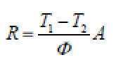
Compute the thermal resistance R, using the following equation:
or the transfer factor T, using the following equation:
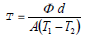
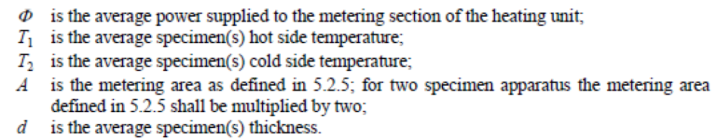
where:
Thermal Conductivity Tester According to EN 12667-Single Specimen Apparatus
- Connection to computer USB port
- Software is included
- Report of software in MS WORD
- Heat flow calculation based on electric power measurement
- Heat flow calculation in software
- Measurement range 10-40 C
- Cold plate temperature room temperature down to 10 C
- Chiller for cold plate is included
- Hot plate temperature room temperature up to 50 C
- According to EN 12667-single specimen apparatus
- Max sample thickness 50mm
- Closed cabin for accuracy of measurements
- Sample size up to 200*200 mm (Other sizes on request)
- Maximum sample thickness 50 mm (Other sizes on request)