8. Requirements
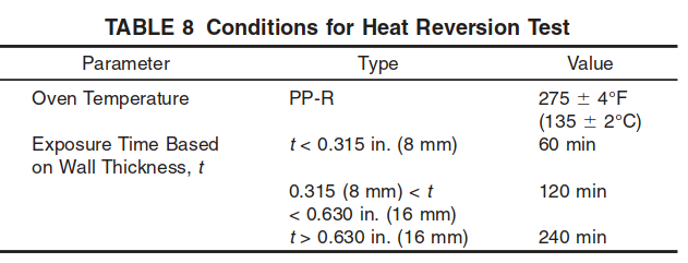
8.1 Longitudinal Reversion—When tested in accordance with ISO 15874-2, at the conditions given in Table 8, the mean relative change in pipe length shall not exceed 2 %.
8.2 Melt Flow Rate (MFR) of Pipe and Fittings—When tested in accordance with D 1238, the MFR of specimens taken from the finished pipe or fittings shall be within 30 % of the MFR of the compound used to produce the pipe or fitting. Two specimens shall be tested, and both shall pass.
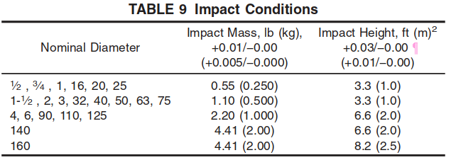
8.3 Impact Strength—When tested in accordance with ISO 3127, 9 of 10 specimens shall pass at the impact level specified in Table 9 at a test temperature of 32 +- 2°F (0 +- 1°C).
8.4 Thermal Stability and Oxidative Induction Time (OIT)— Pipe and fittings shall meet the requirements of 8.4.1–thermal stability by hydrostatic testing, and 8.4.2 oxidative induction time.
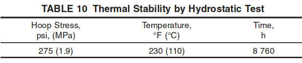
8.4.1 When tested in accordance with Test Method D 1598, pipe and fittings shall not fail at the pressure corresponding to the pipe circumferential stresses and times given in Table 10.If an assembly fails at a joint, the fitting material shall be permitted to be retested in pipe form.
8.4.2 The oxidative induction time (OIT) shall be determined on pipe and fittings in accordance with Test Method D 3895. Two specimens shall be tested and the average OIT of the two shall be at least 80 % of the OIT of the virgin material compound. For those materials which require final blending at the extruder (masterbatch/resin), the 80% OIT requirement shall be based on the OIT of the pipe sample which has also passed the hydrostatic testing of 8.4.1or a pipe sample of the same formulation containing no rework.
NOTE 2—Initial qualification of changes to materials that have met the requirements of this section may be evaluated based on limited hydrostatic testing and comparison of OIT values.
8.5 Hydrostatic Pressure Tests—When tested in accordance with 9.1, at the hoop stresses and temperatures given in Table 11, assemblies of pipe and fittings shall not fail during the test period specified.

8.6 Thermocycling—Plastic-to-metal transition fittings, intended to be used at temperatures above 113°F (45°C) shall not separate or leak during or after being thermocycled 1000 times between the temperatures of 60°F and 180°F (16°C and 82°C). Transition fittings which meet the thermal cycling requirements of ISO 15874-5 for the intended application class are exempt from this requirement. Fittings shall be assembled with pipe per the manufacturer’s instructions, and tested in accordance with 9.2.
9. Test Methods
9.1 Hydrostatic Tests—Test assemblies in accordance with Test Method D 1598, at the hoop stresses and temperatures given in Table 10. An assembly shall consist of at least 4 pipe specimens and 6 fitting joints. For testing valves, the assembly shall include at least 3 valves in the shut-off position (seat test) and 3 valves in the open or partially open position (shell test). Assemblies used in testing of manifolds shall include a minimum of 6 of each type of manifold connection.
9.1.1 Assembly Procedure—The assemblies shall be made in accordance with the manufacturer’s recommended joining procedures and equipment.
9.2 Thermocycling Test Method for Transition Fittings:
9.2.1 Apparatus—A nitrogen or air source capable of maintaining a nominal internal pressure of 100 +- 10 psi (690 +- 69 kPa) on the specimens is required. The immersion system shall consist of two water reservoirs controlled at 60 +- 3.6°F (16 +- 2°C) and 180 +- 3.6°F (82 +- 2°C). The specimens shall be cycled from one reservoir to the other or the hot and cold water shall be alternately cycled over the test specimens automatically and returned to the proper reservoir.
9.2.2 Sampling and Specimen Preparation—Select at random six specimens of the type and size of plastic-to-metal transition fittings to be tested. Assemble the fittings with suitable lengths of pipe or tubing and attach to a common manifold. Assemble strictly in accordance with the instructions of the fitting manufacturer. Close the specimen assembly with any suitable end closures that allow “free-end” mounting and will not leak under the thermocycling conditions, and connect the specimen assembly to the pressure source.
9.2.3 Procedure—Pressure the specimen assembly with nitrogen to 100 +- 10 psi (690 +- 69 kPa). Immerse in 60 +- 3.6°F (16 +- 2°C) water to determine if there are any initial leaks. All leaks shall be eliminated before the thermocycling test is started. Thermally cycle the specimen assembly between 60 +- 3.6°F (16 +- 2°C) and 180 +- 3.6°F (82 +- 2°C) by means of immersion in water using the test cycle given in Table 12. For sizes greater than 1-1⁄2 in. (40 mm), shorter dwell times shall be permitted if it has been demonstrated that the shorter time is sufficient to achieve the test temperature at the internal surface of the fitting. Upon completion of the 1000 cycles, immerse the specimen assembly in 60 +- 3.6°F (16 +- 2°C) water to determine if there are any leaks.
9.2.4 Interpretation of Results—Any evidence of leakage at any one of the transition fittings or separation of any transition fitting from the pipe or tubing constitutes a failure of this test.