
5 Apparatus
5.1 Blanking Die—A die suitable for cutting test specimens.
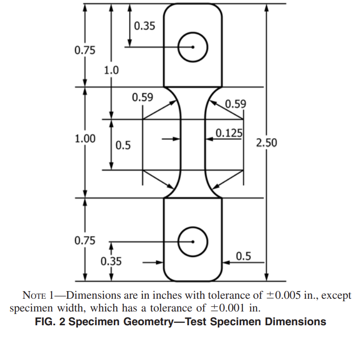
Acceptable dies are: the type L die per Test Method D1822, with holes drilled or punched in the tab areas after die cutting; a die with the dimensions and tolerances specified in Fig. 2.
5.2 Stress-Crack Testing Apparatus—A lever loading machine, with a lever arm ratio of 2:1 to 5:1 similar to that described in Test Method D5397. Alternatively, the tensile load may be applied directly using dead weights or any other method for producing a constant ligament stress. Determine the zero-load offset and lever-arm ratio for each test station, using a force standard that complies with Practices E4. The load on the specimen shall be accurate to 0.5 % of the calculated or applied load. The bath solution temperature shall be set at 122 ± 2°F (50 ± 1°C).
5.3 Notching Device—Notch depth is an important variable that must be controlled. Paragraph 7.2.1 describes the notching procedure and type of apparatus used. The approximate thickness of the blade should be 0.2 to 0.3 mm.
NOTE 1—A round robin was conducted to determine the effect of types of blades on the notch depth. In this study, several types of steel blades (single-edge, double-edge, and so forth) from various manufacturers were used by the round-robin participants. The round robin consisted of seven laboratories using two types of resins molded into plaques. The standard deviation of the test results within laboratories is less than ±10 %.
5.4 Micrometer, capable of measuring to ±0.001 in. (±0.025 mm).
5.5 Microscope, equipped with micrometer or an equivalent device capable of accurately measuring the notch depth.
5.6 Compression-Molding Press and Suitable Chase for Compression-Molding the Specimens, in accordance with Practice D4703.
5.7 Metal Shot, for weight tubes.
5.8 Electronic Scale, for measuring shot weight tubes capable of measuring to ±0.1 g.
5.9 Timing Device, capable of recording failure time to the nearest 0.1 h.
6 Reagents
6.1 The stress-cracking reagent shall consist of 10 % nonylphenoxy poly (ethyleneoxy) ethanol by volume in 90 % deionized water. The solution level is to be checked daily and deionized water used to keep the bath at a constant level.
7 Procedure
7.1 Specimen Preparation:
7.1.1 Compression-mold pellet specimens (virgin resin) or chopped pipe into 0.075-in. (1.9-mm) sheet in accordance with Procedure C of Practice D4703, except that the pellets do not have to be roll-milled prior to being compression-molded. The rate of cooling shall be 27 ± 3.6°F (15 ± 2°C) per minute. If desired, the sheet may be trimmed by 0.6 in. (15 mm) on each side in order to avoid any edge effects. Since pipes have extrusion-induced orientation that can significantly affect the test results, it is necessary to remove the orientation effect by molding into a plaque. Chop and mold a pipe specimen in accordance with the following procedure. Cut 1-in. (25-mm) wide sections from the pipe along its longitudinal axis. To randomize the orientation, cut these sections into smaller pieces until there is about 1 lb (0.5 kg) of material. These sections represent a complete cross-sectional sample from the inside to the outside of the pipe specimen. Compression mold a plaque as previously stated. If different materials are used for the inner and outer wall of dual wall pipe, each wall must be tested separately.
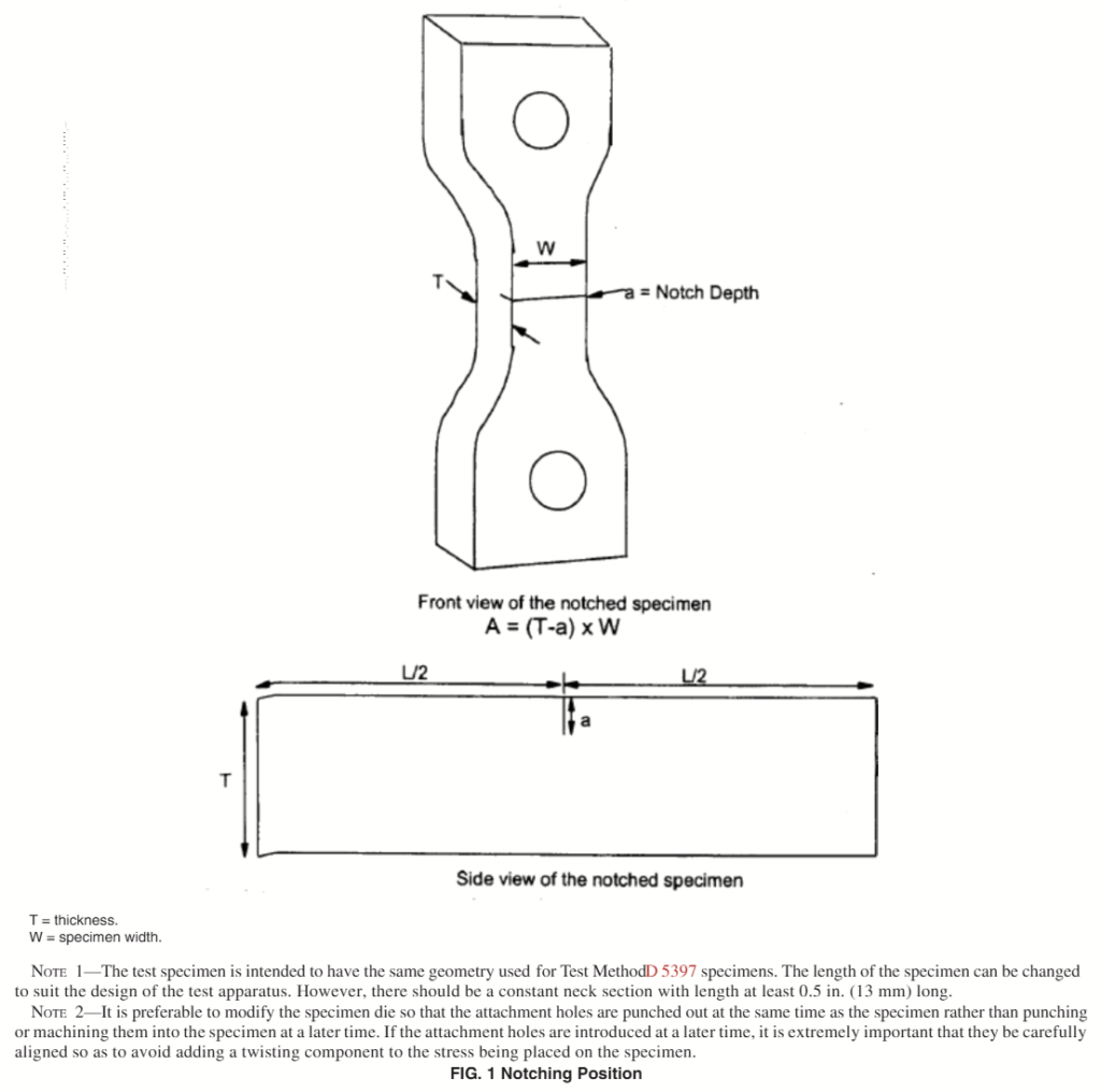
7.1.2 Die cut test specimens from the sheet, and make holes in the specimen as shown in Fig. 1.
7.1.3 Specimen tolerances are as follows:
Length = 2.36 ± 0.01 in. (60.00 ± 0.25 mm)
Width = 0.125 ± 0.001 in. (3.20 ± 0.02 mm)
Thickness = 0.075 ± 0.003 in. (1.90 ± 0.08 mm)
7.2 Notching:
7.2.1 Notch specimens across the center of the 0.125-in. (3.20-mm) wide, 0.500-in. (12.7-mm) long reduced section as shown in Figs. 1 and 2. Cut the notch perpendicular to the plane defined by specimen length and width, and align at a right angle to the direction of load application. Cut the notch at a maximum rate of 0.1 in./min (2.5 mm/min) to a depth of
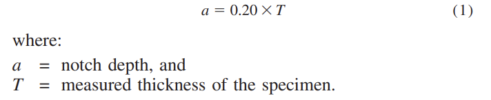
Control notch depth to ±0.001 in. (±0.025 mm) by measuring the notch depth with a microscope. 7.2.2 No single razor blade shall be used for more than ten test specimens.
7.3 Calculation of Test Load:
7.3.1 For each specimen, measure the reduced section width (W), thickness (T), and notch depth (a) to the nearest 0.001 in.
(0.025 mm) using a micrometer and a microscope, or determine the width (W) with a micrometer and determine the ligament thickness directly with a microscope to the nearest 0.0001 in. In the latter case, substitute the ligament thickness in inches for the term (T-a) in Eq 2.
7.3.2 At each loading point, determine the weight that must be hung on the lever arm to produce the required ligament stress directly, by installing a calibrated load cell in the position of the future test specimen and preparing the necessary weight accurately enough that the ligament stress does not vary by more than ±0.5 %. The appropriate load cell reading is as follows:
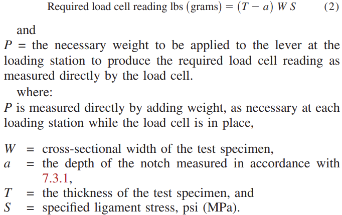
Each test weight so determined is to be labeled (or otherwise correlated to each test position) and applied to the appropriate lever arm on the test apparatus.
NOTE 2—S = the specified ligament-stress. It is the stress at the notch location within each test specimen during the test. It may be expressed as a percent (%) of the reference yield stress of 4000 psi (27.5 MPa). The specified ligament stress is selected at a level that is high enough to provide a differentiation between materials that provide acceptable stress crack resistance and those that do not, within a reasonable testing time period. The reference yield stress of 4000 psi has been selected for all resins meeting AASHTO M 294 density specifications of 0.945 – 0.955 g/cc. This value is near the actual yield stress levels of PE materials representing the upper end of this density range.
7.4 NCLS Testing:
7.4.1 Maintain temperature in the bath at 122 ± 2°F (50 ± 1°C).
7.4.2 Test five specimens at a single ligament stress level.
7.4.3 Determine the weight to be placed on each specimen, and load the weight tubes with shot. Do not attach the shot tube to the lever arm.
7.4.4 Attach the specimens to the loading frame. Take care that the notch is not activated by bending the specimen. Lower the specimen into the bath, and condition the specimens in the bath for at least 30 min.
7.4.5 Reset the specimen timer to zero.
7.4.6 Check that the weight is the correct weight for the particular specimen, and carefully connect the weight tube to the appropriate lever arm for the specimen. Apply the load gradually within a period of 5 to 10 s without any impact on the specimen.
7.4.7 Start the specimen timer immediately after loading.
7.4.8 Record the time to failure of each specimen to the nearest 0.1 h.
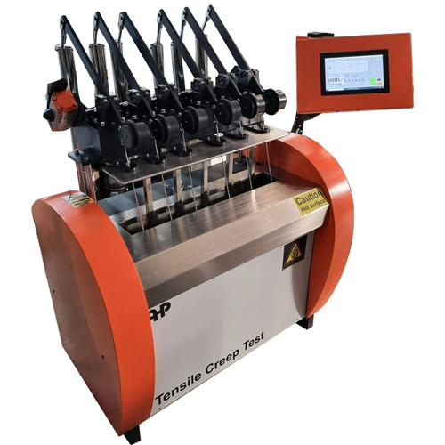
NCLS Tester According to ASTM F 2136 – ECO
- Computerized model
- Windows based software
- software is included
- PLC based
- Circulation system for temperature homogeneity
- Including 6 stations
- One station load cell channel to check forces of each station separately
- Pneumatic based sample elevator
- Lever mechanism force application
- Pneumatic actuator for force application
- Notch making manual press is included
- Press for sample hole clips
- SS304 internal bath
- Stop switch for each channel to record time
- Software according to ASTM F2136
- Computer is not included (Laptop and installation arm will be quoted separately)
- Easy assembly of samples on testing place
- Force application using dead weight mechanism
- Flange type heating elements
- Blanking die and manual press is included
- Notching device with micrometer
- Microscope for notch depth control is not included (Will be quoted separately in case of customer need)
- Compression-Molding Press (Will be quoted separately in case of customer need)
- Training video is included