

5 Apparatus
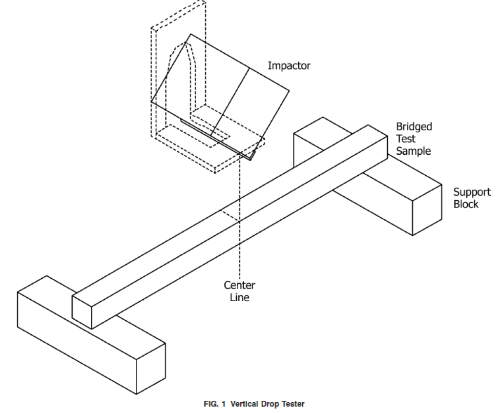
5.1 Option A—Free-Fall Drop Tester, conforming to the conditions specified in 10.2.1 (see Fig. 1).
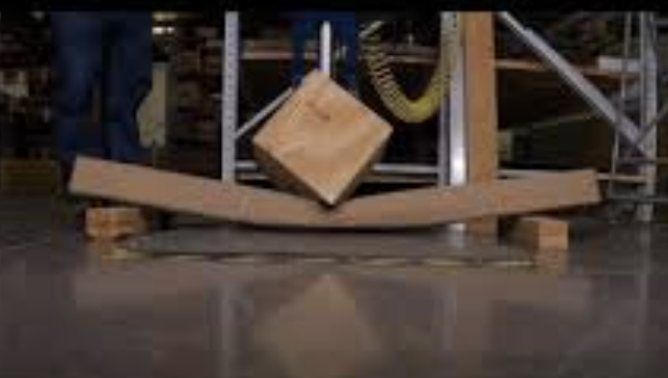
5.1.1 The impactor shall have a mass of 9 lb ± 0.4 lb (4.1 kgw ± 0.2 kgw) and dimensions of 12 in. × 12 in. × 12 in. (300 mm × 300 mm × 300 mm). The impactor shall have the striking edge covered by angle iron. The impactor’s center of gravity shall be aligned with the center of the drop edge(s).
5.1.2 Support Blocks, made from hardwood, nominal 6 in. × 6 in. (150 mm × 150 mm), long enough to support the full width of the largest package to be tested.
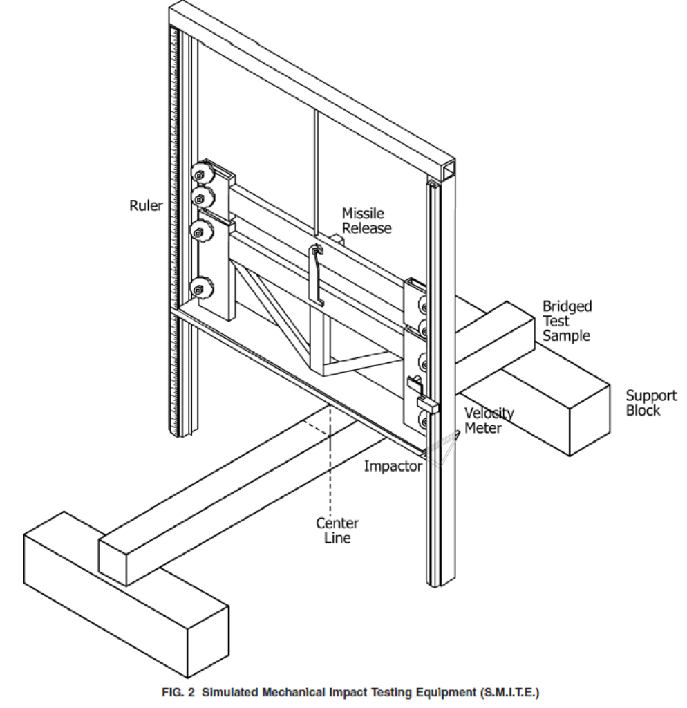
5.2 Option B—Commercial S.M.I.T.E. Tester, using a guided impactor and velocity meter to calculate the theoretical free-fall drop of the missile (see Fig. 2).
5.2.1 S.M.I.T.E. Tester Impactor (missile), fabricated in a V-shape cross-section from a steel flat plate, with a mass of 50 lb ± 0.4 lb (22.68 kgw ± 0.2 kgw) and length of approxi- mately 30 in. (760 mm). The long edges of the missile shall be rounded to a radius of 0.25 in. ± 0.0625 in. (6 mm ± 2 mm).
NOTE 1—The standard S.M.I.T.E. tester is equipped with a variety of interchangeable missiles, providing impact options ranging from flat drop, angle edge drop, half round, half ball, and corner. The total missile assembly, regardless of which face is used, will weigh 50 lb (22.68 kg). Knowing this, the mass of a S.M.I.T.E. tester is always 50 lb (22.68 kg).
5.2.2 Support Blocks, made from hardwood, nominal 6 in. × 6 in. (150 mm × 150 mm), long enough to support the full width of the largest package to be tested.
7 Test Specimens
7.1 When the protective capability of a package is to be evaluated, it is preferable to pack the package with the actual contents for which it was designed (Note 2). When the capability of a box to withstand rough handling is to be evaluated, pack the container with either the actual contents or a load simulating the contents. Regardless of which procedure is used, close the container in the same manner that will be used in preparing it for shipment.
NOTE 2—Where the use of actual contents is not feasible because of excessive cost or danger, a dummy load simulating the contents with respect to dimensions, center of gravity, moment of inertia, density, flow characteristics, etc. shall be used.
7.2 When comparing the performance of various elongated package designs, it is preferable to test empty erected cartons, which are closed and sealed in the same manner that will be used in preparing it for shipment.
7.3 Close and seal the container in the normal manner. Dry and age sufficiently so that any adhesive, protective coatings, sealing tape, etc. will have reached their final normal condition.
10 Procedure
10.1 Determination of Acceptance Criteria—Relate accep- tance criteria to the desired condition of the product and package at the end of the distribution cycle (see Section 9).
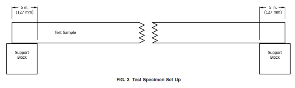
10.2 Option A: Free-Fall Drop Tester—Place the package to be tested on the floor of the drop test apparatus, with it resting on support blocks. The support blocks should be placed parallel to each other and perpendicular to the long axis of the package, so that each end of the package is supported for 5 in. (127 mm) of its length, measured from each end (see Fig. 3).
10.2.1 Position the impactor on the drop table or sling it suitably so that the following conditions are met:
(1) The impactor’s length will be at right angles to the test package length upon contact;
(2) The edge of the impactor shall strike the center of the package so that the plane containing this edge and the center of gravity of the impactor makes no more than a 5° angle with the vertical;
(3) The bottom edge of the impactor is the required drop height above the upper surface of the package being tested; and
(4) The midpoint of the bottom edge of the impactor strikes the midpoint of the impacted face of the package being tested.
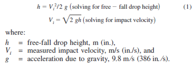
10.2.2 Drop the impactor from a free-fall drop height sufficient to produce a specified impact velocity. Use an impact velocity of 111 in. ⁄s (2.8 m ⁄s).
10.2.3 Obtain the impact velocity of 111 in. ⁄s (2.8 m ⁄s)
from a free-fall drop height of 16 in. (406 mm). Due to energy conservation, the potential energy before drop is equal to the kinetic energy at impact. The kinetic energy at impact will be 12 ft-lb (16.3 J). Equate an impact velocity to a free-fall drop height, or vice versa, as follows:
10.3 Option B: Simulated Mechanical Impact Testing
Equipment (S.M.I.T.E.)—Place the package to be tested on the table of the S.M.I.T.E. test apparatus, with it resting on support blocks. The support blocks should be placed parallel to each other and perpendicular to the long axis of the package, so that each end of the package is supported for 5 in. (127 mm) of its length, measured from each end (see Fig. 3).
10.3.1 Position the impactor on the S.M.I.T.E. tester so that the following conditions are met:
(1) The impactor will strike the package with a long edge, at right angles to the length of the package being tested;
(2) The impactor shall strike the center of the package so that the plane containing this surface and the center of gravity of the impactor makes no more than a 5° angle with the vertical;
(3) The bottom edge of the impactor is the required drop height above the upper surface of the package being tested; and
(4) The midpoint of the bottom edge of the impactor strikes the midpoint of the impacted face of the package being tested.
10.3.2 Drop the impactor from a machine drop height sufficient to generate a specific impact velocity. If no impact velocity is specified, use an impact velocity of 48 in. ⁄s (1.2 m ⁄s). Pre-test drops must be conducted until the test machine indicates the desired impact velocity.
NOTE 3—Different machines will have different frictions in their guide mechanisms. Impact velocity is therefore measured with the velocity sensor. Determine the required impact velocity based on the following relationship:

10.3.3 This impact velocity of 48 in. ⁄s (1.2 m ⁄s) would theoretically be obtained from a free-fall drop height of 3 in. (76 mm); however, due to guide mechanism friction, test machines will require higher machine drop heights sufficient to produce the desired impact velocity. The kinetic energy at impact will be 12 ft-lb (16.3 J).
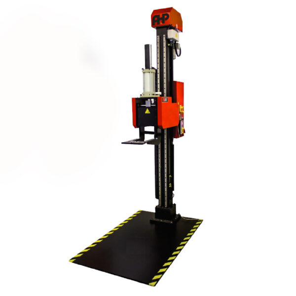
Free-Fall Drop Tester According to ASTM D5265
- 150kg Capacity (Other capacities as customer request)
- Impactor with a mass of 4.1 kg ± 0.2 kg
- Dimension of impactor 300 mm × 300 mm × 300 mm
- Hardwood support blocks with cross section of 150 mm × 150 mm
- Max Drop height: 2m (As customer request)
- Digital adjustment of drop height
- Large Steel base for test surface and mounting 1m x 1.5m x 10mm
- A hand-held control is included
- Precise drop orientations
- Lifting apparatus: Motorized
- Drop Forks: 300mm D x 278mm W (For packages up to 550mm D)- Other sizes as customer request
- Air Supply: 6 bar
- Custom made base plate
- Different fork lengths (as per customer request)
- Top Support Fixture to adjust the angle of drop