
6 Apparatus
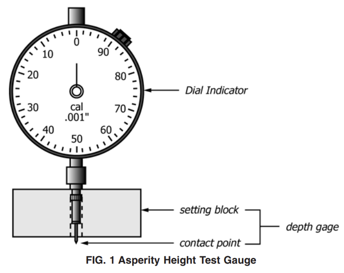
6.1 Depth Gauge—The depth gauge shall consist of three components that conform the requirements of this section; a dial indicator, a setting block and a contact point with extension. 6.1.1 Dial Indicator—capable of measuring to depth of at least 2.5 mm [0.10 in.] with an accuracy of 60.025 mm [0.001 in.].
6.1.2 Setting Block—the setting block shall have a base dimension of 50 mm to 63.5 mm long by 20 mm to 12.7 mm wide [2.0 in. to 2.5 in. long by 0.75 in. to 0.50 in. wide] and a height of 15 mm [0.60 in.].
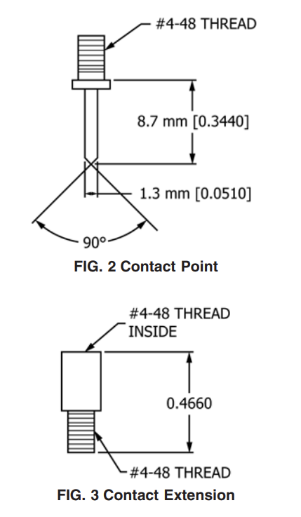
6.1.3 Contact Point with Extension—The contact point is 1.3 mm [0.051 in.] in diameter with the tip tapered to a point. An extension of approximately 17 mm [0.66 in.] is required to achieve the necessary travel beyond the base surface of the setting block. The contact point should protrude at least 10 mm below the setting block when not in use in order to ensure that a competent “zero” setting is achieved. See Figs. 1-3.
6.1.4 The mass of the depth gauge fully assembled with the dial indicator, setting block, contact point with extension should not exceed 300 g.
Procedure
9.1 Test the conditioned specimens in the standard laboratory atmosphere specified in 8.1.
9.2 Place the depth gauge on a flat, rigid supporting surface to zero the contact point with the bottom of the setting block.
9.3 Place the geomembrane specimen being tested on a flat, rigid, supporting surface being vigilant to keep the specimen flat for the measurements. For two side textured geomembranes, measure the asperity height of Side A first. 9.4 Place the depth gauge on the surface of the textured geomembrane specimen, with the long axis of the setting block perpendicular to the machine direction of the roll. Do not to apply downward hand pressure on the gauge as this would compress the asperities under the setting block. Allow the contact point to come into contact with the “low spots” or “valleys,” in between the asperities, or into the indentations, of the textured surface(s). Move the depth gauge slightly on the test specimen to obtain the local maximum reading. Repeat the above within a search radius of approximately 12 mm [0.5 in.] so that a total of three observations are obtained. Record the highest value of the three observations to the nearest 0.025 mm or 0.001 in. as the asperity height determination.
NOTE 1—Be vigilant not to drag the extended contact point while moving the depth gauge laterally across the sample between determinations as this can result in damage to the contact point.
NOTE 2—The parent standard for this procedure, GRI GM-12, originally specified that the local highest asperity measurement is taken for each asperity height determination. This is consistent with procedure for FIG. 1 Asperity Height Test Gauge determining the thickness of a textured geomembrane in accordance with Test Method D5994/D5994M, which specifies that the individual thickness determinations are taken where the “low spots” or “valleys” are the deepest.
9.5 Repeat 9.4 above at the next position,
9.6 Repeat 9.3 through 9.5 on Side B for two side textured geomembrane samples.
Calculation
10.1 Calculate the average asperity height of the sample (the test result) from the ten (10) individual asperity height determinations and record to the nearest 0.025 mm or 0.001 in.
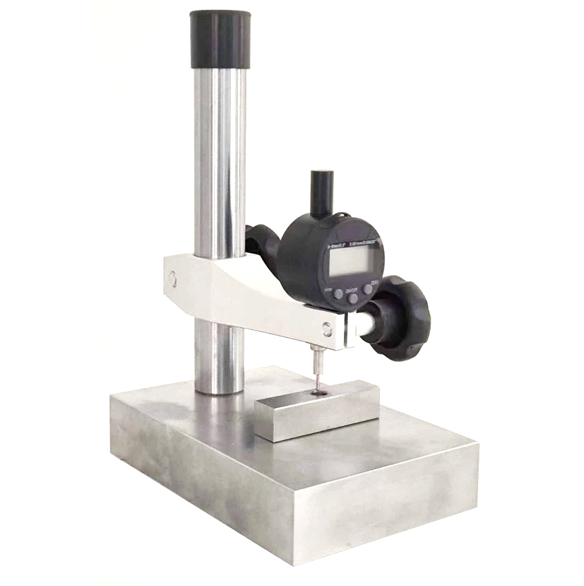
Textured Geomembrane Asperity Height Gauge-ASTM D7466
- Measurement range: 0-8 mm
- Measurement accuracy: 0.001mm
- Probe diameter: 1.3mm
- According to ASTM D7466