6. Apparatus
6.1 Specimen Clamp and Striking Edge:
6.1.1 Type A:
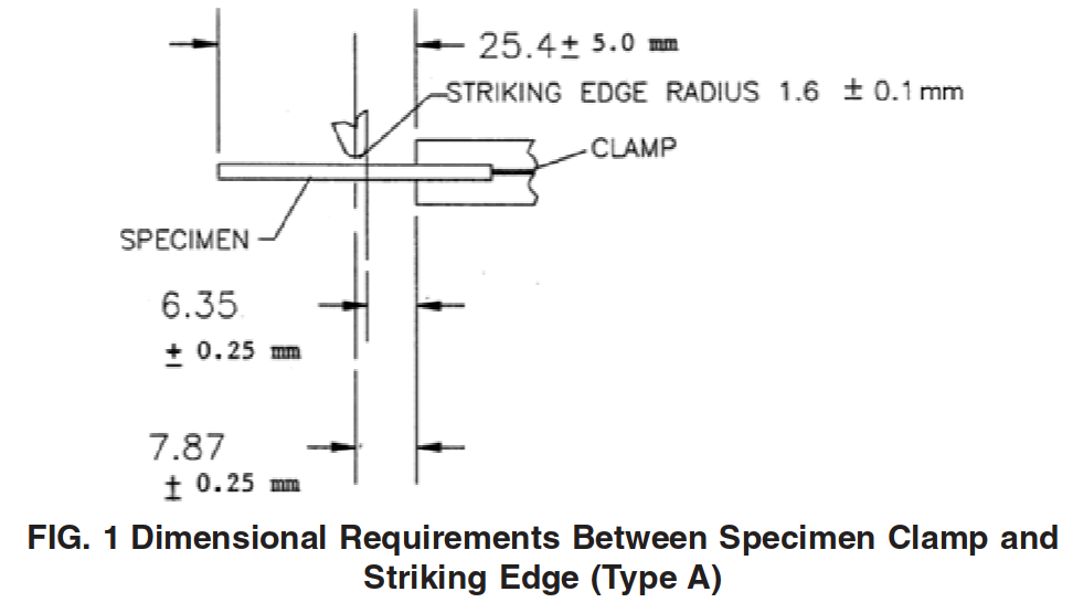
6.1.1.1 Design the specimen clamp to hold the specimen or specimens as a cantilever beam. Each individual specimen shall be firmly and securely held in a separate clamp. The striking edge shall be hardened steel, have a radius of 1.6 +- 0.1 mm and shall move relative to the specimens at a linear speed of 2000 +- 200 mm/s at impact and during at least the following 6.4 mm of travel. In order to maintain this speed on some instruments, it is necessary to reduce the number of specimens tested at one time. The distance between the center line of the striking edge and the clamp shall be 7.87 +- 0.25 mm at impact. The striking edge and specimen clamp shall have a clearance of 6.35 +- 0.25 mm at and immediately following impact. These dimensional requirements are illustrated in Fig. 1. Fig. 2 shows a typical clamp. Use free-fitting clamping screws, 10-32 National Fine Thread.
6.1.2 Type B:
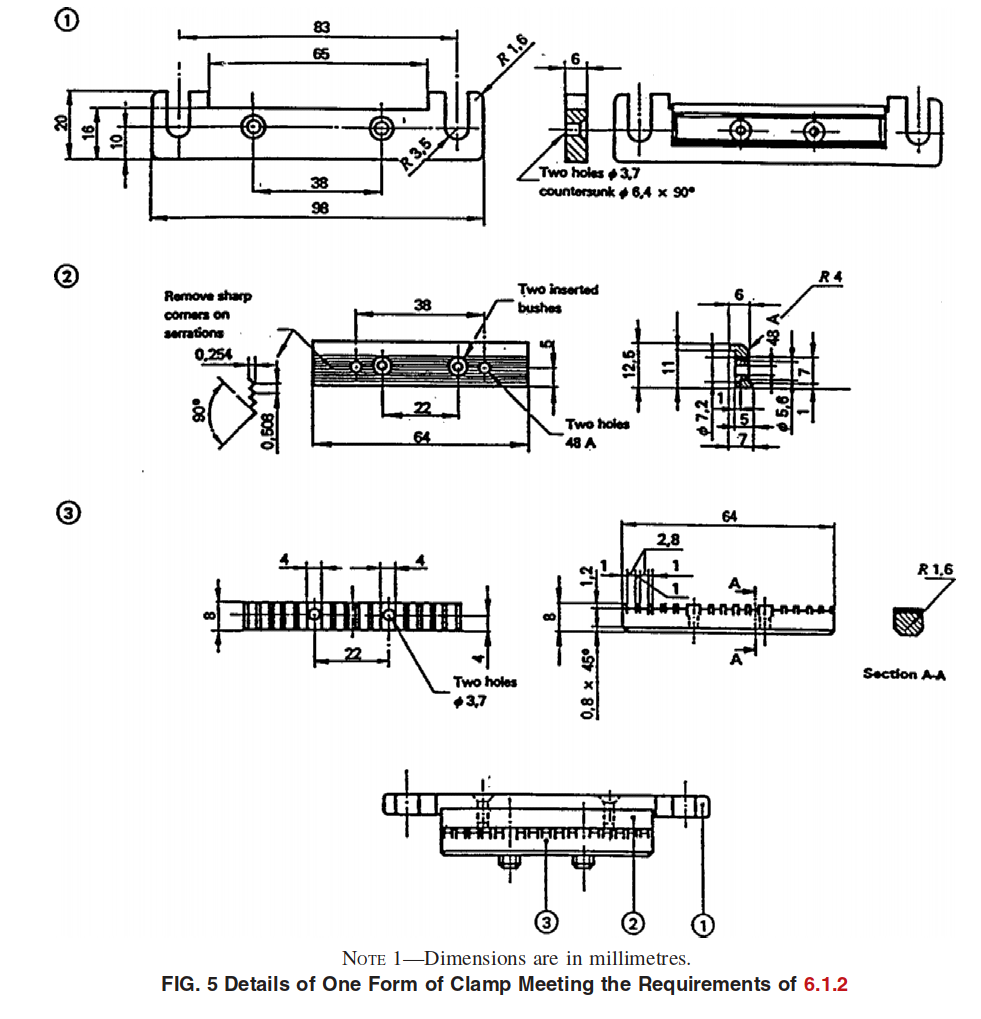
6.1.2.1 Design the specimen clamp to hold the specimen or specimens as a cantilever beam. Each individual specimen shall be firmly and securely held in a separate clamp. The striking edge shall be hardened steel, have a radius of 1.6 +- 0.1 mm, and shall move relative to the specimens at a linear speed of 2000 +- 200 mm/s at impact and during at least the following 5.0 mm of travel. In order to maintain this speed on some instruments, it is necessary to reduce the number of specimens tested at one time. The radius of the lower jaw of the clamp shall be 4.0 +- 0.1 mm. The striking edge and specimen clamp shall have a clearance of 3.6 +- 0.1 mm at and immediately following impact. The clearance between the outside of the striking edge and the clamp shall be 2.0 +- 0.1 mm at impact. These dimensional requirements of the striking edge and clamping device are illustrated in Fig. 3. Fig. 4 shows a typical clamp. Details of the specimen clamp are given in Fig. 5.
6.2 Torque Wrench, 0 to 8.5 N · m.
NOTE 3—Because of the difference in geometry of the specimen clamps, test results obtained when using the Type A specimen clamp and striking member may not correlate with those results obtained when using the Type B apparatus.
6.3 Temperature-Measurement System—The temperature of the heat-transfer medium shall be determined with a temperature measuring device (for example, thermocouple, resistance thermometer, or liquid-in-glass thermometer) having a suitable range for the temperatures at which the determinations are to be made. The temperature-measuring device and the related readout equipment shall be accurate to at least +-0.5°C. The temperature-measuring device shall be located as close to the specimens as possible. Thermocouples shall conform to the requirements of Specification E608/E608M. Resistance temperature devices shall comply with the requirements of Specification E1137/E1137M. Liquid-in-glass thermometers, are described in Specification E1. Use the thermometer appropriate for the temperature range and accuracy required, and calibrate it for the appropriate immersion depth in accordance with Test Method E77.
6.4 Heat-Transfer Medium— Use any liquid heat transfer medium that remains fluid at the test temperature and does not appreciably affect the material being tested. Measurement of selected physical properties prior to and after 15-min exposure at the highest temperature used will provide an indication of the inertness of a plastic to the heat transfer medium.
6.4.1 Where a flammable or toxic solvent is used as the cooling medium, follow customary precautions when handling such materials. Methanol is the recommended heat transfer medium for rubber.
NOTE 4—The following materials have been found suitable for use at the indicated temperatures. When silicone oil is used, moisture from the air will condense on the surface of the oil, causing slush to form. If slush collects on the temperature-measuring device as ice, it will affect temperature measurement. When this occurs, remove the ice from the temperature-measuring device.
6.5 Temperature Control—Suitable means (automatic or manual) shall be provided for controlling the temperature of the heat-transfer medium to within +-0.5°C of the desired value. Powdered solid carbon dioxide (dry ice) and liquid nitrogen are recommended for lowering the temperature, and an electric immersion heater for raising the temperature.
6.6 Tank, insulated.
6.7 Stirrer, to provide thorough circulation of the heat transfer medium.
NOTE 5—Suitable apparatus is commercially available from several suppliers. The striking member may be motor-driven, solenoid-operated, gravity-actuated, or spring-loaded. Equip the motor-driven tester with a safety interlock to prevent striker arm motion when the cover is open.
7. Test Specimen
7.1 Type I (for Type A Apparatus):
7.1.1 Geometry—This type of specimen shall be
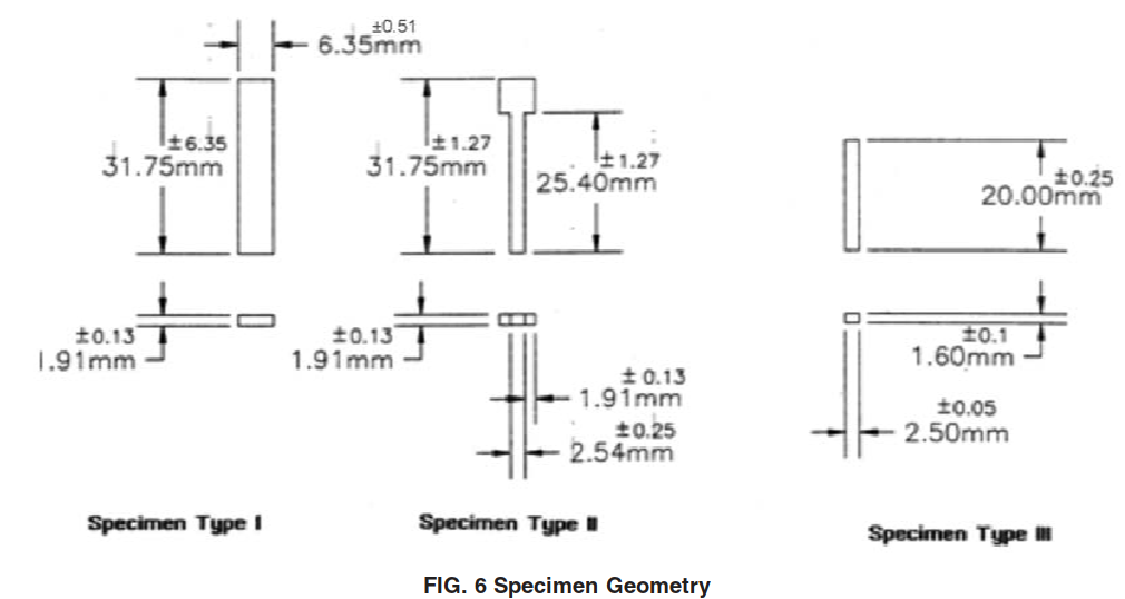
6.35 +- 0.51 mm wide by 31.75 +- 6.35 mm long as illustrated in Fig. 6.
7.1.2 Preparation—Specimens shall be 1.91 +- 0.13 mm thick. Specimens shall be die-punched, cut by hand using a razor blade or other sharp tool, or cut by an automatic machine from flat sheet, or prepared by injection molding.
7.2 Type II (for Type A Apparatus):
7.2.1 Geometry (Modified T-50 Specimen)—This type of specimen shall be T-shaped, as illustrated in Fig. 6. When using this type of specimen, clamp it so that the entire tab is inside the jaws for a minimum distance of 3.18 mm.
7.2.2 Preparation— Specimens shall be 1.91 +- 0.13 mm thick. Specimens shall be die-punched, cut by hand using a razor blade or other sharp tool, or cut by an automatic machine from flat sheet, or prepared by injection molding.
7.3 Type III (for Type B Apparatus):
7.3.1 Geometry—This type of specimen shall be 20.0 +- 0.25 mm long by 2.5 +- 0.05 mm wide and 1.6 +- 0.1 mm thick as illustrated in Fig. 6.
7.3.2 Preparation—Specimens shall be die-punched, cut by hand using a razor blade or other sharp tool, or cut by an automatic machine from flat sheet, or prepared by injection molding.
7.4 Test results will vary according to molding conditions and methods of specimen preparation. It is essential that preparation methods produce uniform specimens. The preferred method of preparation is to use an automatic cutting machine, however specimens that are punched using an arbor press or hydraulically operated press are also acceptable. No matter which preparation method is employed, the specimen edges shall be free of all flash. Specimens that are damaged in any way shall be discarded. If specimens are to be die punched, sharp dies must be used in the preparation of specimens for this test if reliable results are to be achieved. Careful maintenance of die cutting edges is of extreme importance and is obtained by daily lightly honing and touching up the cutting edges with jewelers’ hard Arkansas honing stones. The condition of the die is judged by investigating the rupture point on any series of broken specimens. When broken specimens are removed from the clamps of the testing machine it is advantageous to pile these specimens and note if there is any tendency to break at or near the same portion of each specimen. Rupture points consistently at the same place are the indication that the die is dull, nicked, or bent at that particular position, or that some other defect is present.
8. Conditioning
8.1 Conditioning— Condition the test specimens at 23 +- 2°C and 50 +- 10 % relative humidity for not less than 40 h prior to the test in accordance with Procedure A of Practice D618 for those tests where conditioning is required. In cases of disagreement, the tolerances shall be +-1°C and +-5 % relative humidity.
8.2 Where long-time effects such as crystallization, incompatibility, and so forth, of materials are to be studied, condition the test specimens in accordance with Practice D832.
9. Procedure
9.1 Routine Inspection and Acceptance:
9.1.1 For routine inspection of materials received from an approved supplier, it shall be satisfactory to accept lots on the basis of testing a minimum of ten specimens at a specified temperature as stated in the relevant material specifications. Not more than five shall fail.
9.1.2 It shall be satisfactory to accept elastomeric composition on a basis of testing five specimens at a specified temperature, as stated in the relevant material specifications. None shall fail.
9.2 Determination of Brittleness Temperature:
9.2.1 In establishing the brittleness temperature of a material, it is recommended that the test be started at a temperature at which 50 % failure is expected. Test a minimum of ten specimens at this temperature. If all of the specimens fail, increase the temperature of the bath by 10°C and repeat the test using new specimens. If none of the specimens fail, decrease the bath temperature by 10°C and repeat the test using new specimens. If the approximate brittleness temperature is not known, select the start temperature arbitrarily.
9.2.2 Prior to beginning a test, prepare the bath and bring the apparatus to the desired starting temperature. If the bath is cooled using dry ice, place a suitable amount of powdered dry ice in the insulated tank and slowly add the heat-transfer medium until the tank is filled to a level 30 to 50 mm from the top. If the apparatus is equipped with a liquid nitrogen or CO2cooling system and automatic temperature control, follow instructions provided by the manufacturer of the instrument for preparing and operating the bath.
9.2.3 Mount the test specimens firmly in the specimen clamp. Secure the specimens with a torque wrench. To avoid excessive deformation of the specimens, use a torque suitable for the material being tested.
9.2.4 Mount the specimen clamp in the testing apparatus and lower the specimen clamp into the heat-transfer medium. If dry ice is being used as a coolant, maintain constant temperature by the judicious addition of small quantities of dry ice. If the apparatus is equipped with a liquid nitrogen or CO2cooling system and automatic temperature control, follow the manufacturer’s instructions for setting and maintaining temperature.
9.2.5 After submerging the specimens for 3 +- 0.5 min in the heat-transfer medium, record the temperature and deliver a single impact to the specimens. All specimens shall be impacted within 3.5 min after submersion in the heat-transfer medium.
9.2.6 Remove the specimen clamp from the testing apparatus and remove the individual specimens from the specimen clamp. Allow the specimens to warm up prior to being bent for inspection of cracks by leaving the specimens at room temperature for 1 min or by placing them in lukewarm water for 10 to 15 seconds. Examine each specimen to determine whether or not it has failed. Where a specimen has not completely separated, it shall be bent to an angle of 90° in the same direction as the bend caused by the impact and visually examined for cracks at the bend. Record the number of failures and the temperature at which they were tested.
9.2.7 Determination of Temperature Range:
9.2.7.1 Standard Calculation Method—Increase or decrease the temperature of the bath in uniform increments of 2 or 5°C and repeat the procedure until the lowest temperature at which none of the specimens fail and the highest temperature at which all of the specimens fail is determined. A minimum of four tests shall be conducted in that temperature range. New specimens are to be used for each test.
9.2.7.2 Alternative Graphic Method—Using sets of 10 specimens test them over a range of temperatures where a minimum of four sets result less than a 50 % failure rate and four sets result in a failure rate of greater than 50 %. New specimens are to be used for each test.
10. Calculation
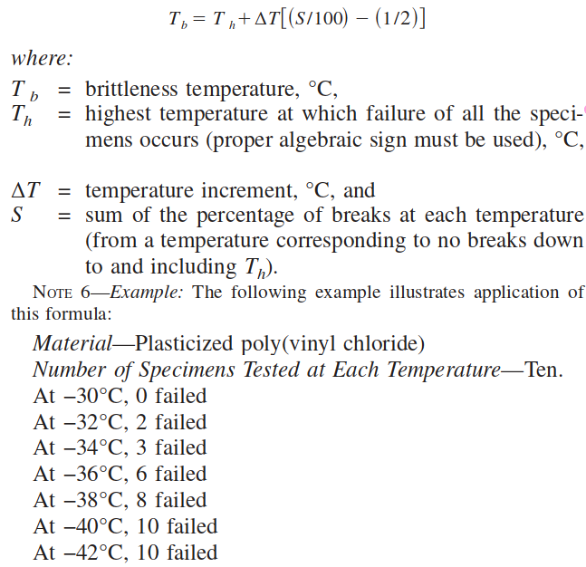
10.1 Standard Method— Using the number of specimens that failed, calculate the percentage of failures at each temperature. Calculate the brittleness temperature of the material as follows:
Brittleness temperature, reported as −35°C.
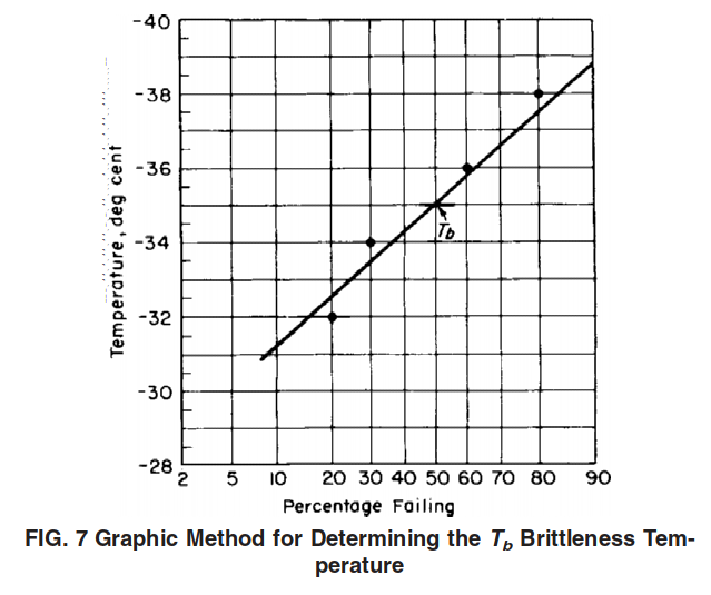
10.2 Alternative Graphic Method—The value reported by this graphic method is essentially the same as that calculated by the standard method described in 10.1, but is obtained without determining either the highest temperature at which all specimens fail or the lowest at which all pass the test. When testing materials that possess a wide temperature range of brittleness transition, the graphic method also requires the testing of fewer sets of samples to determine the brittleness temperature. Select sets of ten specimens each in which both failures and nonfailures occur at four or more temperatures. Choose temperatures above and below the estimated 50 % failure point. Plot the data on probability graph paper with temperature on the linear scale and percent failure on the probability scale. Select the temperature scale so that it represents a minimum of two divisions for each degree. Draw the best fitting straight line through these points. The temperature indicated at the intersection of the data line with the 50 % probability line shall be reported as the brittleness temperature, Tb. Where there is a question of conformance to the relevant material specification, the value obtained according to 10.1 shall be accepted as the Tbvalue.
NOTE 7—The graphic method applied to the data from the example in Note 6 is shown in Fig. 7. The brittleness temperature, Tb, estimated to the nearest degree is −35°C.
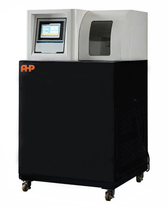
Brittleness Temperature Tester According to ASTM D 746
- Temperature accuracy +-0.5C
- Strike speed 2000mm/s±200mm/s
- Striker travel 40±1mm
- Radius of striker 1.6±0.1mm
- Weight of striker 200±20g
- Clearance between front of striking edge and clamp 3.6±0.1mm
- Clearance between outside of striker and clamp 2±0.1mm
- Radius of lower jaw of clamp 4±0.1mm
- Control using a PC (PC is as option)
- Connection port is USB
- Compressor cooler down to -40C (Lower temperatures need liquid N2 connection-it is as option)
- Report in MS OFFICE

