
6 Apparatus
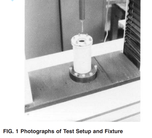
6.1 Tensile/Compression Testing Machine, of the constant rate-of extension (CRE) type, with autographic recorder conforming to the requirements of Specification D 76. See Fig. 1.
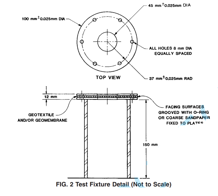
6.2 Ring Clamp Attachment, consisting of concentric plates with an open internal diameter of 45 ± 0.025 mm (1.772 ± 0.001 in.), capable of clamping the test specimen without slippage. A suggested clamping arrangement is shown in Fig. 1 and Fig. 2. The external diameter is to be a minimum of 100
(3.937 ). The diameter of the six holes used for securing the ring clamp assembly is suggested to be 8 mm (0.135 in.) and equally spaced at a radius of 37 mm (2.95 in.). The surfaces of these plates can consist of grooves with O-rings or coarse sandpaper bonded onto opposing surfaces.
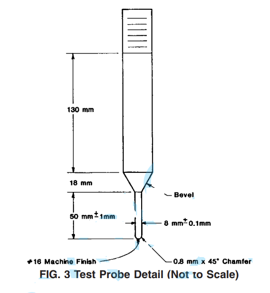
6.3 Solid Steel Rod, with a diameter of 8 ± 0.1 mm (0.315 ± 0.004 in.) having a flat end with a 45° = 0.8 mm (0.315 in.) chamfered edge contacting the test specimen’s surface. See Fig. 1 and Fig. 3.
7 Sampling
7.1 Lot Sample—Divide the product into lots and take the lot sample as directed in Practice D 4354.
7.2 Laboratory Sample—For the laboratory sample, take a swatch extending the full width and of sufficient length along the selvage, from each sample roll so that the requirements of 7.3 and 8.1 can be met. Take a sample that will exclude material from the outer wrap and inner wrap around the core
unless the sample is taken at the production site, then inner and outer wrap material may be used.
7.3 Test Specimens—Select from the laboratory sample the number of specimens directed in Section 8. Minimum specimen diameter is 100 mm (4 in.) to facilitate clamping. Space the specimens along a diagonal on the unit of the laboratory sample. Take no specimens nearer the selvage or edge of the geotextile sample than 1⁄10 the width of the geotextile sample.
10 Procedure
10.1 Select the load range of the tensile/compression testing machine such that the rupture occurs between 10 and 90 % of the full-scale load.
10.2 Center and secure the specimen between the holding plates ensuring that the test specimen extends to or beyond the outer edges of the clamping plates.
10.3 Test at a machine speed of 300 ± 10 mm (12 in. ± 1⁄2 in.)/min until the puncture rod completely ruptures the test specimen.
NOTE 1—The rate of testing specified is not an indication of the performance of the specimen for its end use.
10.4 Read the puncture resistance from the greatest force registered on the recording instrument during the test. For the testing of composite geomembrane materials, there may be a double peak. If so, the initial value should be reported even if the second peak is higher than the first one.