
5 Apparatus
5.1 Pendulum Impulse-Type Testing Apparatus, 5 consisting of the following:
5.1.1 Stationary Clamp.
5.1.2 Movable Clamp, carried on a pendulum, preferably formed by a sector of a wheel or circle, free to swing on a ball bearing or other substantially frictionless bearing.
5.1.3 Stop Catch, for holding the pendulum in a raised position and for releasing it instantaneously.
5.1.4 Indicating Device, for registering the maximum arc through which the pendulum swings when released. The pendulum shall carry a circumferential scale, graduated from 0 to 100 % of the machine capacity so as to read against the pointer the average force required to tear a specimen 43 mm [1.7 in.]. The pointer and scale may be replaced by an electronic digital readout. Digital readouts are available which will give test results directly in millinewtons, directly in grams-force, or in percent of pendulum capacity. With the pendulum in its initial position ready for test, separate the two clamps by an interval of 2.54 mm [0.10 in.]. So align them that the specimen clamped in them lies in a plane perpendicular to the plane of oscillation of the pendulum with the edges of the jaws gripping the specimen in a horizontal line, a perpendicular to which through the axis of suspension of the pendulum is 102.7 ± 0.05 mm [4.044 ± 0.002 in.] in length and makes an angle of 27.5° with the plane of the film specimen. The clamping surface in each jaw shall be at least 25.4 mm [1 in.] in width and at least 12.7 mm [0.5 in.] in depth.
5.1.5 Capacity—Instruments of several capacities, 1960, 3920, 7840, 15 600, 31 360, 62 720 mN [200, 400, 800, 1600, 3200, 6400 gf], and perhaps others are available. These capacities can be achieved by individual instruments, interchangeable pendulum sectors, or augmenting weights.
5.2 Template, Die, or Shear-Type Cutter, for cutting specimens.
5.3 Razor Blades, single-edged, for cutting specimens where a template is used.
5.4 Thickness-Measuring Device—A suitable micrometer, or other thickness gage, reading to 0.0025 mm [0.0001 in.] for measuring the thickness of test specimens. The pressure exerted by the gage on the specimen being measured shall not distort or deform the specimen. For thin films, #0.025 mm [0.001 in.], or films that exhibit visual deformation during measurement, a maximum pressure of 70 kPa [10 psi] is recommended. For thicker or stiffer films, the pressure shall be between 160 and 185 kPa [23 and 27 psi], in accordance with Method C of Test Methods D 374.
6 Test Specimens
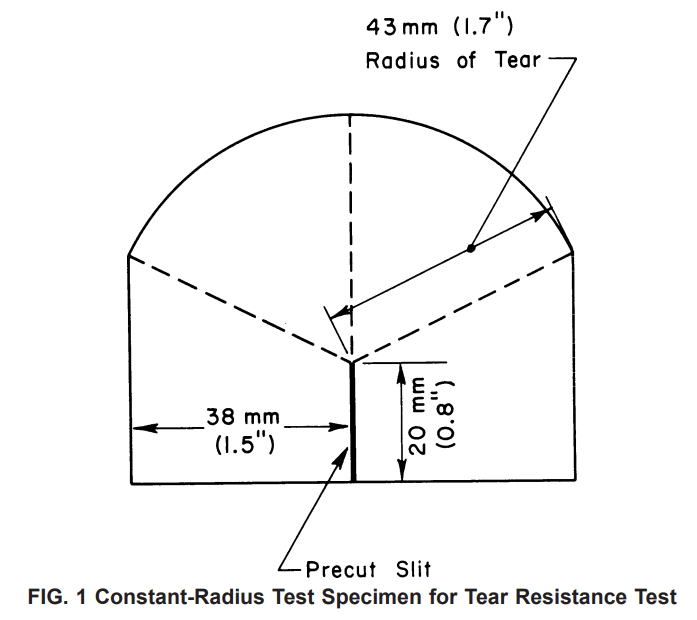
6.1 Test specimens shall be cut, as shown in Fig. 1, to form a constant-radius testing length. This shall be the preferred or referee specimen type since its geometry automatically compensates for the problem of oblique tearing (Note 2 and Note
3). Alternatively, specimens shall be cut to form a rectangle 76 mm [3 in.] or more in width by 63 mm [2.5 in.] in length and plainly marked to denote intended direction of tear. The 63-mm specimen dimension shall be the direction of tear. Two sets of specimens shall be cut from each sample so that their sides are parallel to (1) the machine direction and (2) the transverse direction, respectively, of the material being tested. Enough specimens shall be cut in each direction to provide a minimum of ten tear strength determinations.
NOTE 2—Specimens having constant-radius testing lengths are designed to correct for oblique directional tearing encountered in certain anisotropic, elastomeric films, and nonrigid sheeting. For purposes of specimen selection, oblique tearing is defined as tearing in a curved or straight line that deviates more than 9.5 mm [3⁄8 in.] from the vertical line of intended tear.
NOTE 3—Certain film and sheeting specimens showing oblique tearing may yield data of poor reproducibility because the axis of maximum orientation varies as much as 30° from the nominal machine direction. When this is suspected, the sample may be examined by crossed Polaroid plates to determine this direction of maximum orientation and the specimens cut along the axis of anisotropy for testing parallel and normal to it.
6.2 Where a metal template is used, the film or sheeting shall be placed on a hard surface. The template shall be held over it and the specimens cut out using a single-edged razor blade.
6.3 When the specimen is cut out, a slit 20 mm [0.8 in.] deep may be made at the center of the edge perpendicular to the direction to be tested. This leaves exactly 43 mm [1.7 in.] of tearing length between the end of the slit and the opposite edge of the specimen. This slit may be cut into the specimen after it has been placed in the testing apparatus.
NOTE 4—The pendulum apparatus may be fitted with a sharp-loaded knife to make this slit in the specimen after it has been clamped in the apparatus. The action of the knife must be such as to make a clean slit exactly 20 mm [0.8 in.] into the specimen from the edge.
10 Procedure
10.1 Test not less than ten specimens in each of the principal film or sheeting directions. Measure and record the thickness of each specimen as the average of three readings across its center in the direction in which it is to be torn. Read the thickness to a precision of 0.0025 mm [0.0001 in.] or better except for sheeting greater than 0.25-mm [10-mils] thickness, which is read to a precision of 0.025 mm [0.001 in.] or better.
10.2 One thickness determination per specimen or the average thickness determined by a continuous scanning instrument is acceptable if it can be demonstrated that the overall thickness of the section of the roll from which the specimens were taken does not deviate > ±10 % from the average.
10.3 With the pendulum in its raised position, place the specimen midway in the clamps so that its upper edge is parallel to the top of the clamps and the initial slit (if it was made when the specimen was cut) is at the bottom of and between the clamps at right angles to their top.
10.4 Slit the firmly clamped specimen with the sharp spring-loaded knife if it has not been slit during cutting. Lay the upper testing portion of the specimen over in the direction of the pendulum pivot.
NOTE 5—The work done in tearing a specimen includes a certain amount of work to bend continuously the film or sheeting as it is torn, to provide for the rubbing of the torn edges of the specimen together, and to lift the specimen against the force of gravity. Consequently, it is necessary to specify certain empirical requirements for both the apparatus and the method to keep the additional work not used for tearing to approximately a definite quantity.
10.5 Release the sector stop and tear the specimen. As the sector completes its return swing, catch it with the thumb and forefinger of the left hand, being careful not to disturb the position of the pointer.
10.6 Examine the specimen. If it tore through the constant radius section within an approximate angle of 60° on either side of the vertical line of intended tear, record the pointer reading to the nearest 0.5 unit. If the line of tear was more than approximately 60° from the vertical, reject the reading and test an extra specimen in its place. If rectangular specimens are tested, reject all specimens that tear obliquely more than 9.5 mm [3⁄8 in.] from the vertical line of intended tear. Test extra specimens to replace those rejected. When oblique tearing is frequent, the test may be performed along and normal to the axis of maximum orientation (see Note 3) instead of along machine and transverse directions.
NOTE 6—In addition to tearing in a curved or oblique direction, some specimens may elongate along the line of tear to such an extent that the actual tearing length may be considerably more than the standard 43-mm [1.7-in.] dimension. As the degree or length of this elongation cannot be measured, the data cannot be corrected for its effect. However, when this has occurred, a note should be included in the report of data. This elongation tendency of certain films may cause poorer reproducibility.
NOTE 7—The maximum accuracy of the pendulum apparatus lies in the scale range from 20 to 60. When thin specimens are being tested, it may be advisable to test enough specimens sandwiched together to produce a scale reading between 20 and 60. However, certain specimens in the same sandwich may tear obliquely in opposite directions, which may lead to falsely high results. When this tearing behavior is encountered, single specimens must be tested, even though scale readings may be in the range below 20. If tearing loads are in excess of 60, the augmenting weight attachment may be used to double the capacity of the apparatus or ahigher-capacity pendulum may be used. For thin film, it is recommended that single specimens and a lower-capacity tester be used rather than several specimens and a higher capacity machine. If the scale reading is below 10 on a 200-g pendulum, multiple plies may be used. The number of plies used should be the number required to bring the reading above 10.