
6 Apparatus and Materials
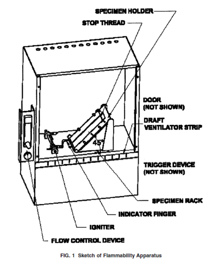
6.1 Flammability Tester,with a separate timer capable of providing flame impingement on the specimen for 1 + 0.01 s as shown in Fig. 1 or an equivalent electrically operated tester equipped with an automatic electric timer, as described in Annex A1. Testers are normally supplied with specimen holders.
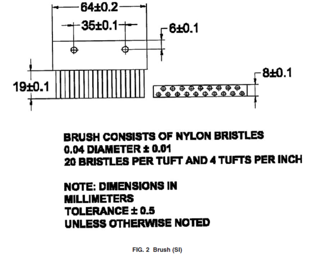
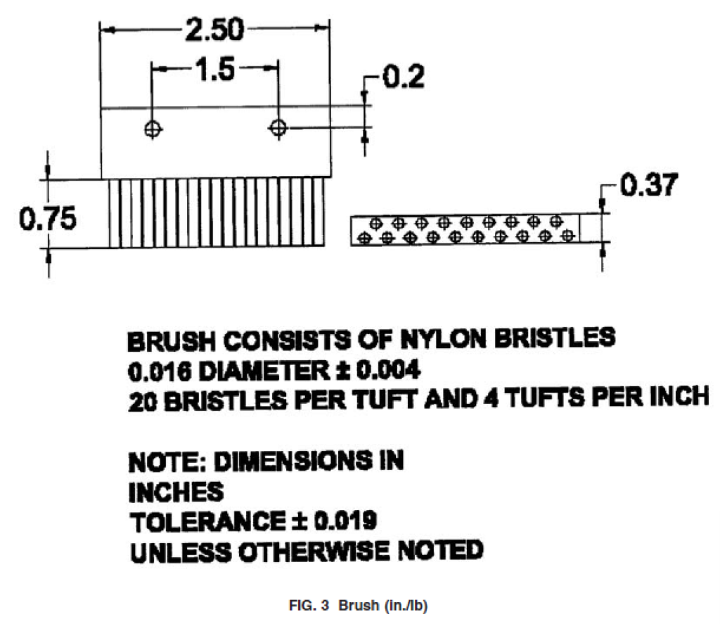
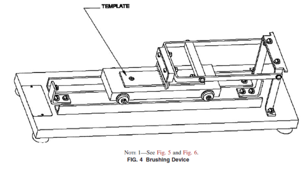
6.2 Brushing Device, as shown in Fig. 2, Fig. 3 and Fig. 4 and described in Annex A1.
6.3 Drycleaning Machine—A commercial dry cleaning machine shall be capable of providing a complete automatic dry-to-dry cycle using perchloroethylene solvent and a cationic drycleaning detergent.
6.4 Laboratory Drying Oven.
6.5 Desiccator,
6.6 Anhydrous Silica Gel,
6.7 Butane, CP.
6.8 AATCC 1993 Standard Reference Detergent.3
6.9 Perchlorethylene, commercial grade.
6.10 Drycleaning Detergent, amine sulfonate type/
(catatonic).
6.11 Cotton Sewing Thread, No. 50, mercerized.
7 Sampling
7.1 Lot Sample—As a lot sample for testing, take at random the number of primary sampling units directed in an applicable material specification or other agreement between the purchaser and the supplier. For fabric, consider rolls of fabric to be the primary sampling units. For garments, consider shipping cartons to be the primary sampling units.
NOTE 2—A realistic specification or other agreement between the purchaser and the supplier requires taking into account the variability between primary sampling units and within primary sampling units so as to provide a sampling plan which has a meaningful producer’s risk, consumer’s risk, acceptable quality level, and limiting quality level. A lot sample normally consists of a very small fraction of the total primary sampling units.
7.2 Laboratory Sample—As a laboratory sample for testing, proceed as follows:
7.2.1 For fabric take a full-width swatch 1⁄2 m (1⁄2 yd) long from the end of each roll of fabric in the lot sample, after first discarding any fabric from the very outside of the roll that contains folds, creases, or any evidence of displaced weave.
7.2.2 For garments, take the number of garments per shipping carton in the lot sample directed in an applicable material specification or other agreement between the purchaser and supplier.
7.3 Test Specimens:
7.3.1 Use exploratory tests as directed in to select the orientation of specimens, the face of the fabric to be tested, and the part of any pattern to be tested so as to maximize the rate of flame spread.
7.3.2 For fabric, cut final test specimens from each swatch in the laboratory sample as directed in 9.1. For fabrics that can be refurbished, cut additional final test specimens from each swatch in the lot sample after the swatches have been refurbished as directed in 9.2. Identify the specimens as coming from a swatch before or after refurbishing.
7.3.3 For garments, cut final test specimens from each garment in the laboratory sample as directed in 9.1. For garments that can be refurbished, cut additional final test specimens from each garment in the lot sample after the garments have been refurbished as directed in 9.2. Identify the specimens as coming from a garment before or after refurbishing.
8 Preparation of Specimens
8.1 Perform tests on the fabric as it will reach the consumer. Accomplish exploratory testing to determine the proper orientation of specimens, face of fabric and part of pattern to be tested by marking and cutting (see 8.2) a single 50 by 150 mm (2 by 6 in.) specimen for each fabric surface, direction, and pattern and testing according to Section 10.
NOTE 3—For fabric with a raised-fiber surface, it is usually found that the long dimension of the specimen needs to be parallel with the lay of the pile, and that flame spread is most rapid when progressing against the lay of the pile.
8.2 Marking and Cutting, General Directions—Mark out the required number of specimens (See Section 9) each 50 by 150 mm (2 by 6 in.) on the surface opposite that to be tested, with the long dimension in the direction in which burning is most rapid as established in the preliminary trials (See 8.1). Long dimension is the longer length of test specimen for purposes of this method. In cases where it is difficult to determine the direction of the lay of the nap, it is possible to identify it following the method stated in the CPSC Laboratory Manual: Laboratory Test Manual for 16 CFR Part 1610. Identify the end of each specimen toward which, and on the surface of which flame spread is most rapid by attaching a staple to it. Then cut specimens from the fabric. Place any identification markings on the side and end opposite of that to be tested.
9 Specimens for Final Testing
9.1 Test all fabrics as received per 9.1.1. If fabric is Class 3 as-received (See Sections 11 and 12) proceed to Section 13. If fabric is Class 1 or Class 2 as-received (See Sections 11 and 12) proceed to 9.1.2.
9.1.1 Fabric as Received—Cut five specimens (see, however, 11.1) as directed in 8.2, in addition to the one previously tested in the preliminary trials. Specimen is a section of sample to be tested having specific dimension. Five or ten specimens are required to be tested for a complete test. (Refer to Section 11 for additional information as to when an additional five specimens are required.)
9.1.2 Refurbished Fabric—Cut a swatch large enough to provide five or ten specimens, as indicated in 11.1, with allowance for shrinkage in dry cleaning and washing, and subject the swatch to drycleaning and washing procedures as per 9.2. Specimen is a section of sample to be tested having specific dimension. Five or ten specimens are required to be tested for a complete test. (Refer to Section 11 for additional information as to the need for an additional five specimens.)
9.2 Refurbishing:
9.2.1 Drycleaning:
9.2.1.1 Solvent: Perchloroethylene, commercial grade Detergent class: Cationic.
Cleaning time: 10 to 15 min.
Extraction time: 3 min.
Drying Temperature: 60 to 66°C (140 to 150°F).
Drying Time: 18 to 20 min.
Cool Down/Deodorization time: 5 min.
9.2.1.2 Perchloroethylene is toxic and a suspected carcinogen, and the usual precautions for handling chlorinated solvents need to be taken. Perchloroethylene is to be used only under well-ventilated conditions. The solvent is nonflammable.
9.2.1.3 Samples shall be dry cleaned in a load that is 80 % of the machine’s capacity. If necessary, ballast of clean textile pieces or garments, white or light in color, and consisting of approximately 80 % of wool fabric pieces and 20 % cotton pieces shall be used.
9.2.2 Wash and dry the fabric once in a home type washer in accordance with AATCC 124 – 2006 sections 8.2.2, 8.2.3 and 8.3.1(A). Use wash water temperature (IV), 49 ± 3°C, (120 ± 5°F); Normal / Cotton Sturdy Cycle 18 6 1 gal water level. A maximum wash load of 3.63 kg (8 lbs) shall be used. Tumble dry, Durable Press, using an exhaust temperature of 66 ± 5°C (150 ± 10°F), and a cool down time of 10 min. 9.2.3 Cut five or ten specimens (as indicated in 11.1) of refurbished fabric as directed in 8.2.
NOTE 4—Drycleaning followed by laundering is intended to remove additives which could affect the burning characteristics of the textile.
9.3 Specimen Mounting—Clamp the specimens individually in the specimen holders of the flammability tester. Insert the specimen in the frame so that the bottom edge of the specimen coincides exactly with the lower edge of the longest (top) frame. This can be accomplished by laying the specimen on the bottom (shorter) frame so that the top edge of the specimen coincides exactly with the top of the cut out portion of the frame. The stapled or marked end is placed in the upper position during test. “Bull Dog” clips are usually used to hold the two halves of the specimen holder together, but other methods are acceptable. Double-faced tape is often used on the bottom half of the specimen holder to help hold the specimen taut and in place.
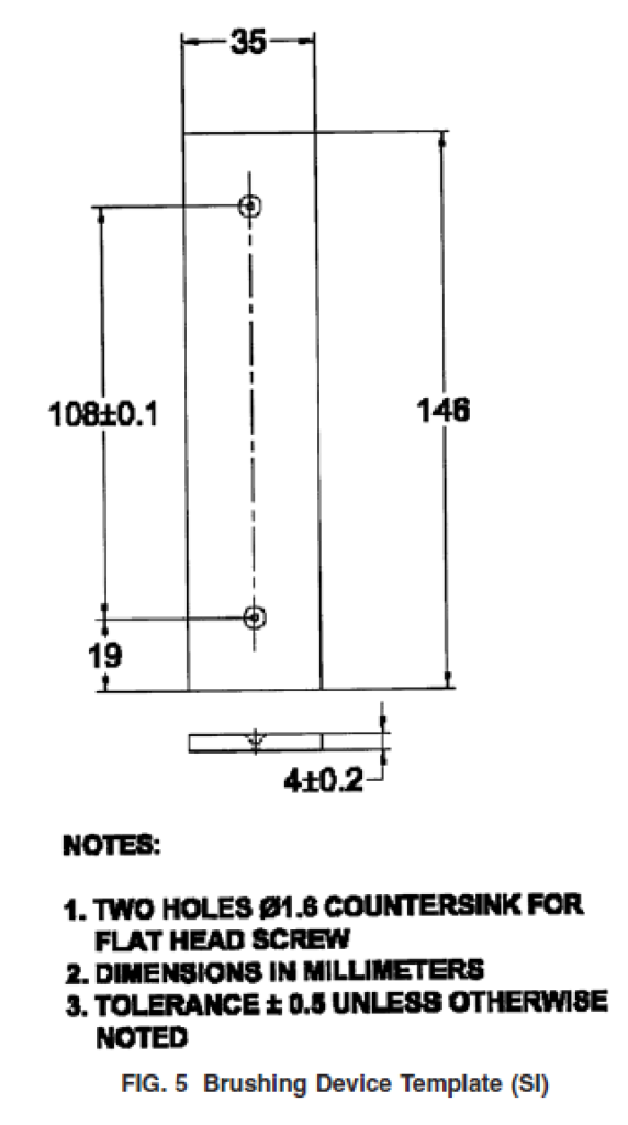
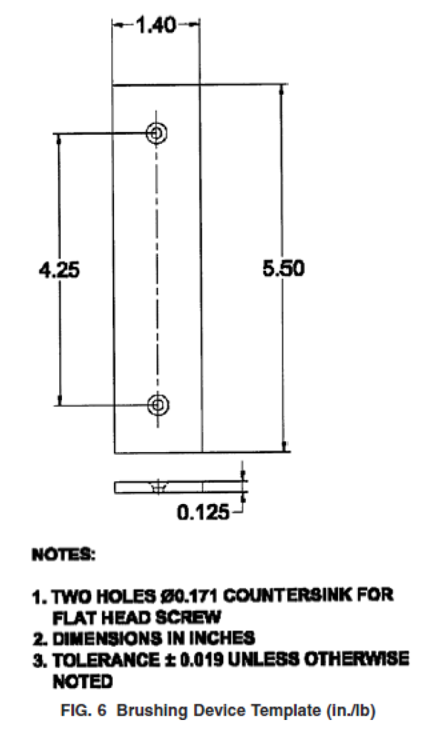
9.4 Brushing—Brush each specimen having a raised fiber surface with the specimen mounted in a specimen holder. The purpose of the metal plate or “template” on the carriage of the brushing device is to support the specimen above the level of the top surface of the specimen holder during the brushing operation. Accordingly, such template dimension needs to be as outlined in Fig. 5 and Fig. 6.
9.5 Dry the mounted specimens in a horizontal position in an oven for 30 min at 105 ± 5°C (221 ± 3°F), remove from the oven, and place over anhydrous silica gel or equivalent in a desiccator until cool, but for not less than 15 min.
NOTE 5—Oven drying eliminates the effects of moisture content inherent in some fibers. Many fabrics have been shown to ignite in shorter exposures to ignition sources, and burn with higher flame spread rate when oven dried, than when tested at a higher moisture content. This is attributed to the moisture content in some fibers at higher relative humidity conditions. In 9.5, oven drying of specimens is specified because of test simplicity and reproducibility of test results.
10 Procedure
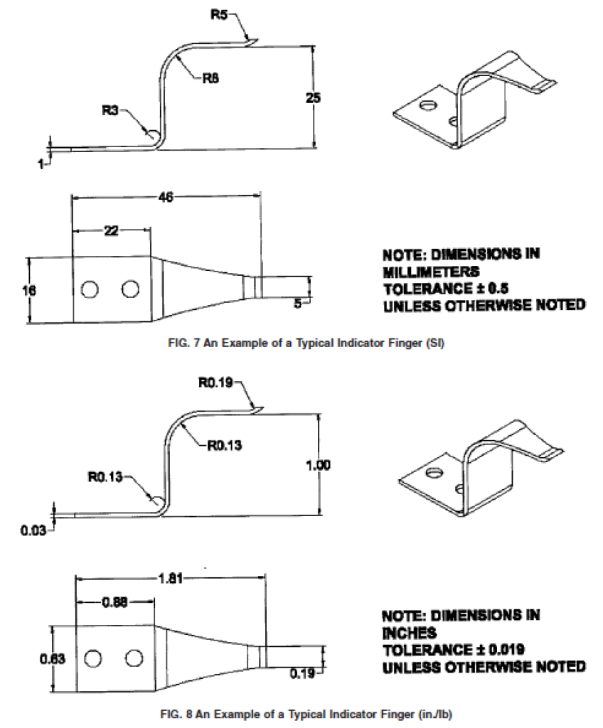
10.1 Adjust the position of the rack of the flammability tester (Fig. 1) with a holder and trial specimen (not a prepared specimen) in position, so that the tip of the indicator touches the face of the specimen. Place the specimen holder in the chamber so that the longest frame is on top. Adjust the burner and sample holder so that, with the indicator touching the face of the specimen, the flame is applied to the vertical center of the specimen, 19 ± 0.2 mm (3⁄4 ± 0.019 in.) from the bottom of the specimen and with the burner face 8 ± 0.2 mm (5⁄16 ± 0.019 in.) from the face of the specimen. See Figs. 7-12
10.2 Open the control valve of the fuel supply and allow approximately 5 min for the air to be driven from the fuel line. Ignite the gas and adjust the flame to a length of 16 mm (5⁄8 in.) measured from its tip to the opening in the gas nozzle. See Fig. 13 and Fig. 14.
10.2.1 Verify the accuracy of the timing mechanism for the flame impingement of 1 ± 0.1 s without a test specimen in place, using an instrument capable of timing within 0.05 s.
10.3 Remove a mounted specimen from the desiccator and place it in position on the rack in the chamber of the apparatus (Fig. 1). Place the stop cord 9.5 ± 0.2 mm (3⁄8 ± 0.019 in.) above and parallel to the lower surface of the top plate of the specimen holder. Hook the stop weight in place close to and just below the stop weight thread guide. Expose the test specimen to the flame within 45 s of the time it was removed from the desiccator.
NOTE 6—This configuration can be achieved easily and reproducibly with the use of L-shaped guides on the specimen holder and an additional thread guide popularly referred to as a “sky hook.” The essential condition, however, is the uniform height of three-eighths of an inch for the stop cord and not the number, placement, or design of the thread guides.
10.4 Close the door of the apparatus. Set the timer at zero. Conduct the test in a draft-free enclosure with the apparatus at room temperature.
10.5 Activate the starting lever or button. This starts the timing mechanism and applies the flame to the specimen for a period of 1 s. Timing is automatic, starting upon application of the flame and ending when the weight is released by the burning of the stop cord.
NOTE 7—Reference to base fabric charring or fusion for textiles having raised fiber surfaces refers to charring or fusion as a result of heat generated by surface burning or surface flash, and specifically excludes charring or fusion as a result of application of the igniting flame.
11 Calculations
11.1 Calculate the arithmetic mean flame-spread time of the five specimens. If this time is less than 3.5 s or if some of the specimens do not burn, test five additional specimens. The time of flame spread shall then be the average time for the ten specimens, or for as many of them that burn.
ANNEX
(Mandatory Information)
A1. DESCRIPTION OF APPARATUS
A1.1 Flammability Tester
A1.1.1 The flammability tester (Fig. 1) consists of a draftproof ventilated chamber enclosing a standardized ignition medium, a specimen rack, and an automatic timing device.
A1.1.2 The draft-proof metal chamber prevents air circulation around the specimen rack and flame, but permits free ventilation for rapid oxidation. The chamber is 368 mm (141⁄2 in.) wide by 216 mm (81⁄2 in.) deep by 356 mm (14 in.) high.
There are twelve 12.7 mm (1⁄2 in.) holes equidistant along the rear of the top closure. A ventilating strip is provided at the base of the sliding glass door in the front of the chamber.
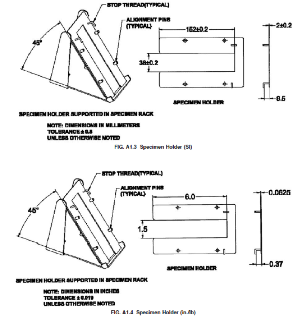
A1.1.3 The specimen rack (Fig. A1.1, Fig. A1.2, Fig. A1.3 and Fig. A1.4) provides support for the frames in which the specimens are mounted. The angle of inclination is 45°. This specimen rack is mounted to allow adjustment to be made for the thickness of the specimen in relation to the flame front. An indicating finger is provided, the fore part of which touches the specimen when the rack is correctly adjusted.
A1.1.4 The specimen holder (Fig. A1.3 and Fig. A1.4) consists of two 2 mm (0.06 in.) matched metal plates with clamps mounted along the sides, between which the specimen is fixed. The plates are slotted and loosely pinned for alignment. The two plates of the holder cover all but 38 mm (11⁄2 in.) of the width of the specimen for its full length. The specimen holder is supported in the draft-proof chamber on the rack at an angle of 45°. Five specimen holders are provided.
A1.1.5 Design must allow specimen adjustment from outside of the flammability chamber.
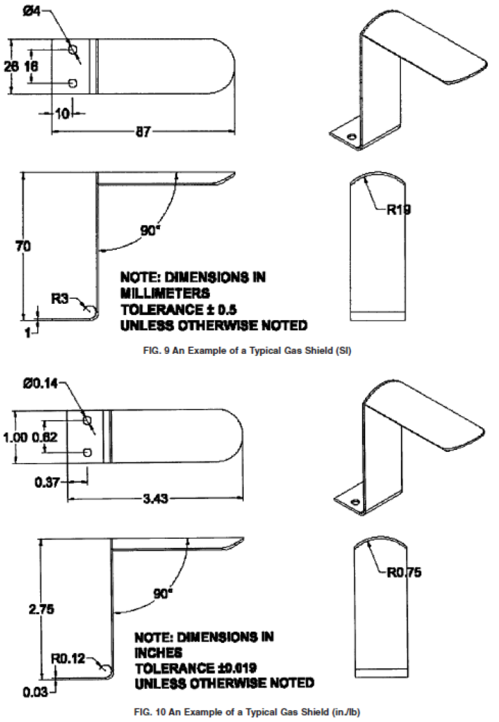
A1.1.6 The ignition medium consists of a mechanism driven gas jet formed around a 26-gauge hypodermic needle. The gas jet is protected by a shield.
A1.1.7 The stop cord is stretched from the spool through suitable thread guides provided on the specimen frame and chamber walls, permitting the lacing of the cord in the proper position 127 mm (5 in.) from the point where the center of the ignition flame impinges on the test specimen. The stop cord is a No. 50 mercerized sewing thread.
A1.1.8 Aweight attached by means of a clip to the stop cord in dropping stops a timer.
A1.1.9 The glass door slides in grooves at the front of the chamber. The design shall incorporate a means of holding the sliding door in an open position for insertion of the test specimen holders.
A1.1.10 A sensitive fuel control valve regulates the fuel supply at the tank. The valve ends in a 12.7-mm (1⁄2-in.) male connection for attachment to the standard No. 4 butane cylinder of 0.9-kg (2-lb) capacity.
A1.1.11 The manometer consists of a U-shaped glass tube
cut into the gas line to register the gas pressure delivered to the
microburner.
A1.1.12 The design shall enbody controls to facilitate the performance of the test, such as power controls and a start test control. The actuation mechanism moves the microburner to its forward most position and automatically starts the timer at impingement. The weight, when released by severance of the cord, stops the timer.
A1.1.13 The timing device consists of a timer, driving mechanism and weight. The timer, by means of special attachments, is actuated to start by connection with the gas jet.
A trigger device activates the flame impingement, causing the driving mechanism to move the gas jet to its most forward position and automatically starts the timer at the moment of flame impact with the specimen. The falling weight, when caused to move by severance of the stop thread, stops the timer. Time shall be read directly and recorded as a burn time. Read burn time to 0.1 s. An electronic or mechanical timer can be used to record the burn time, and electro-mechanical devices (that is, servo-motors, solenoids, micro-switches, and electronic circuits, in addition to miscellaneous custom made cams and rods, shock absorbing linkages, and various other mechanical components) can be used to control and apply the flame impingement.
A1.2 Brushing Device
A1.2.1 The brushing device (Fig. A1.1 and Fig. A1.2) consists of a base board over which a small carriage is drawn. This carriage runs on parallel tracks attached to the edges of the upper surface of the base board. The brush is hinged with pin hinges at the rear edge of the base board and rests on the carriage vertically with a pressure of 150 gf (0.33 lbf).
A1.2.2 The brush consists of two rows of stiff nylon bristles mounted with the tufts in a staggered position. The bristles are 0.41 mm (0.016 in.) in diameter and 19 mm (3⁄4 in.) in length. There are 20 bristles per tuft and four tufts per inch. A clamp is attached to the forward edge of the movable carriage to permit holding the specimen on the carriage during the brushing operation.
A1.2.3 After the specimen has been put in place on the carriage and fastened by means of the clamp, the brush is raised, the carriage pushed to the rear, and the brush lowered to the face of the specimen. The carriage is then drawn forward by hand at a uniform rate.
Textile Flame Tester According to ASTM D 1230