

Nonwoven geotextiles are used in many geomembrane projects as protection or cushioning layers. Placed between the geomembrane and surfaces such as stone, aggregate or concrete, these materials help reduce the risk of localized damage. Evaluating their quality requires more than measuring mass per unit area: tensile strength, strain, tear resistance, puncture resistance and ultraviolet durability also need to be assessed.
GRI-GT12(b) specifies a set of properties and acceptance values for nonwoven geotextiles used to protect geomembranes. This article explains the equipment needed to cover the specified tests and the technical criteria that should guide equipment selection.
Technical basis: The acceptance table and manufacturing quality control provisions in this article are based on GRI-GT12(b), Revision 2, dated November 15, 2016. Machine capacity, travel, load cell combinations and software features identified as engineering recommendations are equipment selection advice, rather than requirements directly imposed by GRI. Final test settings must be checked against the complete text of the test method and the edition accepted for the contract.
1. Scope and Required Tests
The specification addresses manufacturing quality control, or MQC. It applies to nonwoven geotextiles, commonly made from polypropylene, polyester or polyethylene. Needle-punched construction is common, although the specification is not limited to a single manufacturing process. It does not provide project design guidance or installation procedures. Particular applications may require additional tests or more restrictive acceptance values.
| Property | Method in the specification table | Main equipment | Reported result |
|---|---|---|---|
| Mass per unit area | ISO 9864 | Balance and cutting tools with a verified specimen area | g/m² |
| Tensile strength and strain at maximum force | ISO 10319 | Tensile testing machine, wide grips and extensometer | kN/m and % |
| Trouser tear strength | ISO 13937-2 | Tensile testing machine, suitable tear grips and cutting template | kN |
| Static CBR puncture | ISO 12236 | Testing machine with a ring clamp and plunger fixture | Maximum force and corresponding displacement |
| Strength retention after UV exposure | ASTM D7238 | UV/condensation chamber and equipment for strength testing before and after exposure | Retention after 500 light hours, % |
Reference clarification: The supplied specification writes the mass per unit area method as “ISO 09864”; this refers to ISO 9864. Its referenced documents section also retains the earlier wording for trapezoidal tear. However, the property table on page 6 and revision history on page 7 identify trouser tear according to ISO 13937-2 for Revision 2. An Elmendorf tester or a trapezoidal tear fixture alone does not cover this table entry.
Although the document is titled the “ISO Version,” its UV exposure method is ASTM D7238. Equipment scope should therefore follow the actual property table.
2. Acceptance Values for the Geotextile Classes
The following table reproduces the SI values in the supplied revision. All properties except UV resistance are expressed as minimum average roll values, or MARV. UV strength retention is specified as a minimum value.
| Property / Class | 350 | 400 | 600 | 800 | 1000 | 2000 |
|---|---|---|---|---|---|---|
| Mass per unit area, g/m² | 350 | 400 | 600 | 800 | 1000 | 2000 |
| Tensile strength, kN/m | 16 | 21 | 27 | 32 | 36 | 45 |
| Strain at maximum force, % | 50 | 50 | 50 | 50 | 50 | 50 |
| Trouser tear strength, kN | 0.42 | 0.51 | 0.66 | 0.89 | 0.96 | 1.32 |
| Maximum CBR puncture force, kN | 3.1 | 3.6 | 4.1 | 4.9 | 7.6 | 11.0 |
| Plunger displacement at maximum force, mm | 38 | 38 | 38 | 38 | 38 | 38 |
| UV strength retention after 500 light hours, % | 70 | 70 | 70 | 70 | 70 | 70 |
For the CBR test, 38 mm refers to displacement at maximum force. It is not the machine travel requirement or a tensile elongation percentage. Likewise, strain at maximum force must be distinguished from strain at rupture.
3. Selecting the Main Mechanical Testing Machine
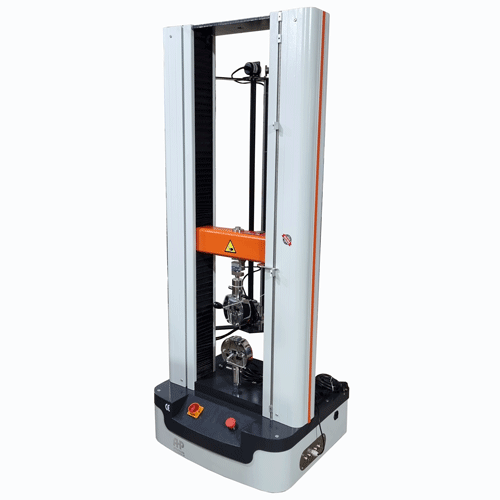
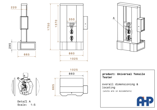
A universal testing machine with appropriate accessories can perform wide-width tensile, trouser tear and static CBR puncture tests. It must measure tensile force and the compressive force applied through the puncture fixture, and allow the grips, plunger and load cells to be changed.
Determining Machine Capacity
Tensile strength is reported as force per unit width. The corresponding force can be estimated using:
F (kN) = T (kN/m) × b (m)
For a specimen width of 200 mm, a strength of 45 kN/m corresponds to 9 kN. This is an equipment sizing calculation. Acceptance limits alone should not determine final machine capacity, because actual products may be stronger than the minimum values.
| Class | Force corresponding to the minimum tensile strength at 200 mm width | Minimum CBR puncture force |
|---|---|---|
| 350 | 3.2 kN | 3.1 kN |
| 400 | 4.2 kN | 3.6 kN |
| 600 | 5.4 kN | 4.1 kN |
| 800 | 6.4 kN | 4.9 kN |
| 1000 | 7.2 kN | 7.6 kN |
| 2000 | 9.0 kN | 11.0 kN |
Engineering recommendation: A dual-column machine rated at 20 kN is a reasonable starting point for evaluating all listed classes, provided actual peak forces and the ratings of every accessory remain within the permitted operating range. A 50 kN machine may be considered for stronger products or a broader future testing scope. A 10 kN machine cannot reach the minimum puncture force specified for Class 2000.
Load Cells, Accuracy and Travel
- Main load cell: Select a 20 or 50 kN load cell for tensile and puncture testing according to the machine rating and actual products.
- Tear load cell: A 2 or 5 kN load cell may be more suitable for forces near the specified 0.42 to 1.32 kN range. Its capacity must exceed actual peak forces.
- Force accuracy: Specify the verified calibration range under ISO 7500-1, Class 1 or better, in the purchase requirements. Display resolution alone does not establish measurement accuracy.
- Suggested travel: Approximately 500 to 800 mm of usable travel is a starting point for selection. Grip dimensions, fixture height, actual strain and travel needed to complete the test must be checked separately. These travel values are recommendations, not GRI requirements.
- Motion control: Select stable, adjustable speed control, travel limits, overload protection and an emergency stop. Force capacity alone is insufficient to establish suitability.
Calibration must cover each load cell and operating mode over the range actually used. A single high-capacity load cell may be used across tests only if its accuracy at lower forces has also been verified.
4. Wide-Width Tensile Test Equipment for ISO 10319
The grips must hold the full width of a nonwoven geotextile specimen. For the common 200 mm specimen configuration, provide a usable grip width of at least 200 mm. Final specimen geometry and initial jaw separation must follow the selected edition of the method.
Verified provisions in ISO 10319:2024: The method uses constant crosshead speed and force accuracy of Class 1 or better. Speed is selected to produce a strain rate of (20 ± 5) %/min in the true specimen gauge length. Strain is measured between two specimen reference marks using an extensometer; their nominal spacing is normally 60 mm, and extensometer accuracy is ±2% of the indicated reading. Specimen gauge length must be distinguished from jaw separation. Products with low strain have a separate speed-setting provision. [2]
Grip selection recommendation: Mechanical, pneumatic or hydraulic compression grips with jaw faces suitable for geotextiles can be considered. Adequate, uniform clamping force matters more than the grip type designation. The grip must prevent slipping, fibre cutting and excessive local stress concentration. Adjustable clamping pressure and interchangeable jaw faces help accommodate different masses per unit area and material structures.
Extensometer recommendation: Video or optical extensometers are worth considering for soft materials with high strain because they reduce mechanical contact with the specimen. Gauge length and measuring range must match the expected strain. For example, 50% elongation over a 60 mm gauge length represents a 30 mm increase in reference-mark spacing; this is a measuring-range estimate.
The software should use actual specimen width, maximum force and corresponding strain to report strength in kN/m. Machine direction and cross-machine direction results should be recorded separately. Reporting stress in MPa, or calculating strain exclusively from crosshead movement without verifying method compliance, is insufficient for this application.
5. Trouser Tear Test Equipment for ISO 13937-2
In a trouser tear test, the two legs of a slit specimen are gripped separately. As the jaws move apart, the tear propagates. The result is determined by evaluating curve peaks according to the method; the single highest peak in the entire record is not automatically the standard tear result.
Basic method parameters: Speed is 100 ± 10 mm/min, grip gauge length is 100 ± 1 mm, and electronic data collection is at least eight readings per second. The basic specimen is 200 × 50 mm with a 100 mm slit; tolerances are ±2 mm for length, ±1 mm for width and ±1 mm for slit length. Annex D provides a wide-width procedure requiring agreement and documentation. At least five specimens per direction are specified. Grips must prevent slipping and damage. [3]
Equipment selection: Provide grips suitable for the specimen portion being held, a cutting and slit template, an appropriately ranged load cell, and tear analysis software. For thick or highly tear-resistant geotextiles, agree the specimen geometry and whether the wide-width procedure is required before manufacturing the final templates.
Software recommendation: Adjustable raw data recording, for example at 100 Hz, is useful together with peak review, evaluation-region marking and saved filter settings. A 100 Hz rate is an equipment recommendation; the basic method minimum is 8 Hz. Heavy filtering can remove genuine force fluctuations and change the tear result.
Changes in tear direction, grip slippage or fibre pullout should be investigated, with reasons for invalidating specimens recorded. Trouser, Elmendorf and trapezoidal tear results cannot be converted into one another without a technical basis and agreement.
6. Static CBR Puncture Fixture for ISO 12236
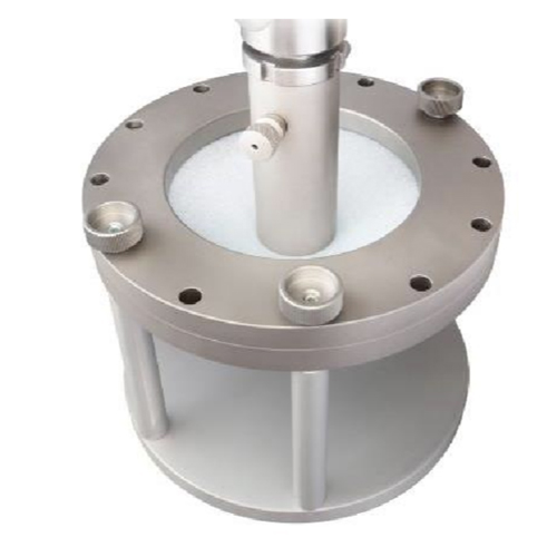
A flat-ended plunger pushes against a specimen secured in a ring clamp. The machine records the force-displacement curve through puncture. The GRI table requires both maximum force and displacement at that same point.
- Plunger and ring: The familiar configuration uses a nominal 50 mm plunger diameter and a nominal 150 mm internal clamp opening. Dimensional tolerances, edge radius, ring thickness and construction details must be taken from the drawings in the contractually selected edition.
- Speed capability: Include the ability to operate around 50 mm/min in the purchase specification. Confirm the exact test speed and tolerance against the complete method.
- Specimen clamping: Ring fastening must prevent slipping and accommodate the intended range of specimen thicknesses.
- Alignment: The plunger, clamp and force axis must be aligned. Contact between the plunger and fixture body affects the result.
- Clearance: Provide sufficient space below the specimen for plunger movement through the end of the test. Fixture depth cannot be selected solely from the 38 mm acceptance value.
- Mechanical rating: Rings, supports and connections must be designed for the maximum operating force. Load cell capacity does not establish fixture strength.
Engineering recommendation: A machine and fixture rated for 20 kN can be considered as an initial configuration for all table classes. Before acceptance, run a real test with a thick, strong specimen to check slippage, clearance and travel.
Define displacement zero and contact detection according to the method, and assess the influence of machine compliance. CBR puncture is a static test and is not replaced by a falling-weight impact test. The GRI note permits pyramid puncture according to ASTM D5494 as an alternative only where suitable calibration has been established and agreed by the parties.
7. Mass per Unit Area Equipment for ISO 9864
Mass per unit area is calculated by dividing specimen mass by specimen area:
Mass per unit area (g/m²) = Mass (g) / Area (m²)
For example, 100 cm² equals 0.01 m². A specimen weighing 6 g over that area has a mass per unit area of 600 g/m². This illustrates the calculation only; it does not authorize that specimen area for ISO 9864 testing. Specimen area and quantity must be selected from the method.
- Balance: Select capacity according to the heaviest specimen. Readability of 0.001 g is a useful starting point, but actual error and uncertainty must be checked against specimen mass.
- Cutting tools: Provide a die or template with a verified area, a sharp blade and a cutting surface suitable for thick nonwovens. Do not select a small-area conventional GSM cutter without checking the ISO method.
- Dimensional verification: Provide measuring tools for area verification and reference weights for balance checks.
- Preparation: Cut specimens without stretching and record roll identification, sampling location and conditioning.
Balance pan size and cutting capability also matter for larger specimens or Class 2000 products. Evaluate mass per unit area independently of mechanical properties: achieving the specified mass does not establish tensile or puncture resistance.
8. Selecting a UV/Condensation Chamber for ASTM D7238
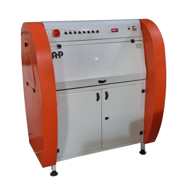
The supplied GRI revision requires at least 70% strength retention after 500 UV light hours. Light hours are different from total elapsed test time. Where a program includes dark or condensation stages, total elapsed time is longer.
ASTM D7238 uses fluorescent UVA-340 lamps under controlled environmental conditions. [4] A chamber containing UV lamps without control of exposure and environmental conditions does not provide full method coverage.
- Light source: UVA-340 lamps arranged to expose specimens uniformly.
- Irradiance control: Measurement and control of spectral irradiance using suitable sensors and calibration. Nominal lamp wattage does not establish irradiance at the specimen surface.
- Temperature control: Sensors and control appropriate to the method, including a black-panel system where required by the selected edition.
- Condensation: Generation and control of the condensation stage, water-level management and operating-condition recording.
- Programming: Automated exposure and condensation stages, a separate light-hour counter and recording of interruptions or power failures.
- Specimen holders: Geotextile mounting without unintended shading and with sufficient material for subsequent strength testing.
- Traceability: Records of irradiance, temperature, duration, lamp identification, replacement and calibration.
Purchase specification recommendation: Ask the supplier for a compliance matrix against the contractual edition of ASTM D7238, identifying irradiance, reference wavelength, temperature, stage durations and achievable tolerances. The supplied GRI document does not set out these numerical operating conditions. A generic UV program or lamp count and wattage alone cannot establish the required configuration.
Strength Testing After Exposure
Control and exposed specimens should come from comparable material and be tested by the same strength method. Retention is calculated as:
Retention (%) = (Strength after exposure / Strength before exposure) × 100
For example, a reduction from 30 to 22.5 using the same method and units gives 75% retention. Page 6 of the supplied specification does not identify the detailed post-exposure strength-test procedure or specimen geometry. These must be clarified in the test plan and contract. Do not automatically assume that a 200 mm wide tensile specimen is the appropriate UV evaluation specimen without checking the required procedure.
9. Specimen Preparation and Laboratory Environment
Reliable results depend on preparation as well as equipment. Temperature, humidity, sampling location, specimen direction and conditioning duration must be defined for each method. Do not assume identical environmental requirements for mass, tensile, tear and puncture tests without checking their references.
- A cutting table large enough for wide, thick geotextiles, with separate templates for each method.
- A calibrated temperature and humidity recorder and a stable conditioning area.
- Specimen labels identifying product, batch, roll, machine or cross-machine direction and sampling date.
- Length and width measuring tools; if thickness testing is added, a geotextile thickness gauge applying the specified pressure.
- Storage of control specimens away from sunlight, contamination and mechanical damage.
Select the quantities of tensile, puncture and mass specimens from their respective methods. GRI does not prescribe one common specimen count for all tests. The UV specimen quantity and control-testing plan should also be settled before exposure begins.
10. Software and Reporting
Recommended laboratory software features:
- Separate method profiles for ISO 10319, ISO 13937-2 and ISO 12236, including edition identification.
- Recording of force, displacement, time and extensometer signals, with raw data retention.
- Tensile strength calculation in kN/m, strain at maximum force and tear peak analysis according to the selected method.
- Maximum puncture force and plunger displacement at that point.
- Records of invalid specimens and reasons, while preserving their history.
- Mean, standard deviation and coefficient of variation, with separate results for each direction.
- Product-class acceptance limits and unit checks during comparison.
- PDF reports and tabulated data, including roll identification, environment, accessories, load cell and calibration status.
- For UV, the exposure program, actual light hours, interruptions, strength-test method and retention percentage.
When using newer method editions, software must support any revised strain definitions or curve features. Changing the standard designation in a report header alone does not establish compliance with the new edition.
11. MARV and Product Acceptance
The supplied GRI specification defines MARV for normally distributed data as the typical mean minus two standard deviations of a defined population of quality control results:
MARV = Mean − 2 × Standard deviation
For example, if production has a mean tensile strength of 35 kN/m and a standard deviation of 2 kN/m, its MARV is 31 kN/m. Although the mean is 35, the MARV does not reach the Class 800 requirement of 32 kN/m. Controlling production variability therefore matters alongside improving the mean.
A manufacturer’s MARV is based on documented results for a defined production population. It is different from the average of a few specimens from one roll. Under Clause 7.2, acceptance is determined by comparing the average result of specimens within a sample with the specified MARV limit. UV is evaluated against its minimum strength-retention requirement rather than automatically treating it as a MARV property.
Where the purchaser does not perform testing, manufacturer certification must be supported by a documented quality control program. Roll identification, material composition, product designation and production information should be traceable. Retesting and rejection procedures are defined within the manufacturer’s quality system.
12. Suggested Equipment Package for the GRI-GT12(b) Table
| Package component | Engineering recommendation | Key selection criterion |
|---|---|---|
| Dual-column universal testing machine | Start by evaluating 20 kN; consider 50 kN for expansion | Actual peak force and usable accessory space |
| Load cells | Main cell matched to the machine; 2 or 5 kN tear cell | Verified calibration range and force margin |
| Wide-width tensile grips | Usable width for a 200 mm specimen, with adjustable clamping pressure | No slippage or grip-induced failure |
| Extensometer | Optical, video or mechanical type suitable for nonwovens | Direct strain measurement and sufficient range |
| Tear grips and templates | Matched to the agreed ISO 13937-2 geometry | Standard peak analysis and tear-path recording |
| CBR fixture | Plunger and rings to the selected method drawings | Alignment, specimen clamping and clearance |
| Balance and mass-per-area tools | Balance for actual specimen mass and verified-area cutting tools | Area selected according to ISO 9864 |
| UV/condensation chamber | UVA-340, irradiance and temperature control, condensation and logging | Documented ASTM D7238 compliance |
| Preparation and environment | Cutting table, templates, temperature and humidity recorder | Method-specific conditioning and specimen quantities |
| Software and documentation | Reports, raw data, method profiles and calibration certificates | Roll traceability and method edition identification |
A laboratory purchasing only a universal machine and mass-per-area equipment can cover the mechanical and physical entries with the correct accessories. UV coverage requires an appropriate chamber or outsourcing to a qualified laboratory. Full specification coverage also depends on sampling, quality control, acceptance and certification procedures.
13. Technical Checks Before Purchase and Equipment Acceptance
- Identify product class, polymer, mass per unit area, actual peak forces and strain.
- State the GRI revision and all test-method editions in the purchase specification.
- Separate the standard scope of supply from optional items, especially the second load cell, extensometer and fixtures.
- Provide real product specimens for demonstration tensile, tear and CBR tests.
- Check force calibration range, displacement accuracy, extensometer performance and speed stability.
- For UV, verify the exposure program, light-hour recording, strength evaluation procedure and irradiance calibration.
- Obtain a complete report with raw data and independently check its calculations.
- At delivery, check cutting tools, plunger, rings, grips, lamps, sensors, training and maintenance instructions.
14. Additional Tests Outside the Main Table
Thickness, permeability, opening size, chemical resistance, creep or protective performance under actual project conditions may be required by the designer or purchaser. These are outside the acceptance table of the supplied GRI-GT12(b) revision and should be identified as additional scope. Thickness or permeability equipment should not be described as mandatory for this package merely because the product is a geotextile.
Base equipment selection on actual products: a machine with sufficient capacity, suitable accessories, verified strain measurement, a controlled UV chamber and traceable reporting. Together, these support evaluation of the table properties. Selection of the appropriate geotextile class for a project still depends on design and application conditions.