

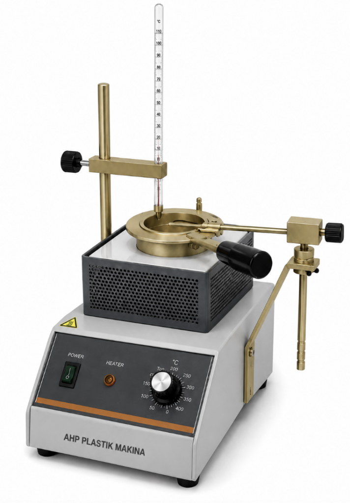
The Tag Open-Cup Flash Point Tester is designed for the determination of the flash point of cutback asphalt in accordance with ASTM D3143.
The method applies to cutback asphalts having flash points below 93°C and is based on controlled heating of the sample in an open glass test cup while a small test flame is passed across the vapor space at specified temperature intervals.
The flash point is defined as the lowest temperature at which application of the test flame causes a distinct flash of the vapor above the surface of the test sample.
Test Principle
A prepared asphalt sample is placed in the specified glass test cup, which is installed inside a temperature-controlled metal bath.
The sample is heated at a slow and controlled rate. As the temperature approaches the expected flash point, a calibrated test flame is passed horizontally across the center of the test cup at specified temperature intervals.
Heating and flame application continue until the vapor generated above the sample produces a distinct momentary flash.
The corresponding sample temperature is recorded as the:
Tag Open-Cup Flash Point
This controlled procedure provides an indication of the volatility and flammability characteristics of the solvents used in cutback asphalt and can also indicate contamination by lower-flash-point solvents.
Apparatus Configuration
ASTM D3143 specifies a Tag Open-Cup Tester consisting principally of:
- Heat-resistant glass test cup
- Metal bath
- Thermometer and vertical thermometer holder
- Leveling device
- Controlled bath heating system
- Ignition taper and swivel mechanism
- Test-flame size reference
- Draft protection system
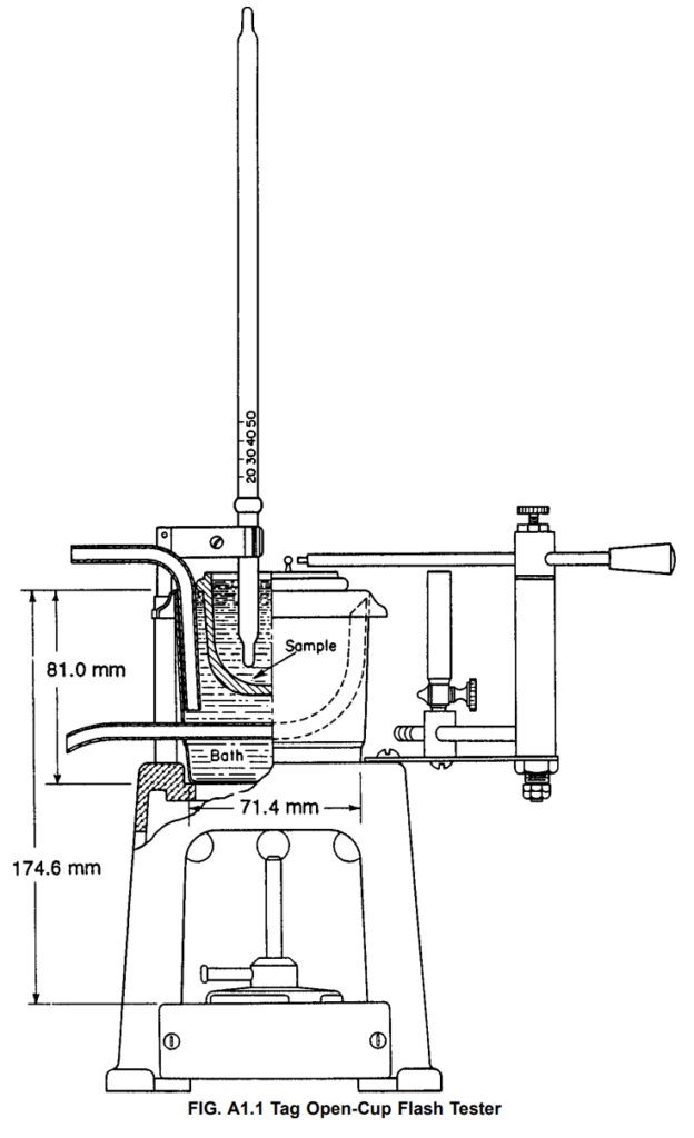
The complete arrangement is illustrated in Figure A1.1 . The drawing shows the glass sample cup installed inside the surrounding bath, the thermometer entering the sample vertically, and the ignition taper arranged to sweep horizontally over the center of the cup.
Glass Test Cup
The sample container shall be a molded clear-glass cup manufactured from annealed, heat-resistant glass and free from surface defects.
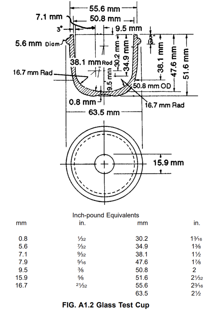
The detailed geometry of the test cup is shown in Figure A1.2 of the standard.
Key dimensions shown in the standard drawing include:
- Maximum outside diameter: approximately 63.5 mm
- Upper outside diameter: approximately 55.6 mm
- Upper inside diameter: approximately 50.8 mm
- Overall height: approximately 51.6 mm
- Internal bottom radius: 16.7 mm
- Central bottom feature: 15.9 mm
- Specified wall and rim geometry according to Figure A1.2
Because vapor generation and the interaction between the flame and vapor space depend on the exposed sample surface and cup geometry, use of a correctly dimensioned test cup is an essential part of reproducing the ASTM D3143 test conditions.
Metal Bath and Bath Liquid
The glass test cup is installed inside a metal bath, specified in the apparatus description as a copper bath, preferably equipped with a constant-level overflow.
The overflow arrangement maintains the bath-liquid level approximately:
3.2 mm below the rim of the glass test cup
The selection of bath medium depends on the expected flash point.
For flash points up to 79°C:
Water
For flash points above 79°C:
Water/Glycol Solution – 1:1
Before testing, the bath liquid should be at least:
16°C below the probable flash point
of the material being tested.
When the test cup is installed, the bath liquid should reach the overflow tube.
Temperature Measurement
ASTM D3143 specifies a Pensky-Martens low-range thermometer covering approximately:
−7°C to +110°C
and conforming to the requirements for ASTM Thermometer 9C.
The thermometer must be supported firmly in a vertical position.
Its position relative to the test cup is precisely controlled.
The thermometer is located approximately halfway between the center and the edge of the cup, on a line passing through:
the center of the cup and the pivot of the ignition taper.
Vertically, the thermometer is adjusted so that:
the bottom of the thermometer bulb is 6.3 mm above the inner bottom of the test cup.
Correct thermometer position is important because the reported flash point corresponds to the measured temperature of the test material at the instant the first distinct flash occurs.
Sample Filling Level
The quantity of sample inside the cup is not arbitrary.
A dedicated leveling device or gauge is positioned on the rim of the test cup and the sample is added until its surface just contacts the pointer of the gauge.
The resulting sample surface is approximately:
3.2–3.3 mm below the upper rim of the test cup.
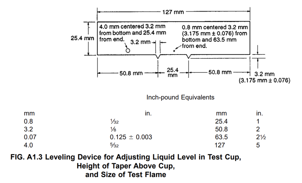
Figure A1.3 on page 5 provides the geometry of this leveling device. The same gauge is also used for checking the height of the ignition taper and the size of the test flame.
Maintaining the specified liquid level is essential because changing the distance between the sample surface and ignition flame changes the vapor-space geometry and can affect the measured flash point.
Ignition Taper and Test Flame
The ignition system consists of a small straight blow-pipe type gas burner mounted on a swivel mechanism.
ASTM D3143 specifies approximately:
- Taper tip diameter: 1.6 mm
- Taper orifice diameter: 0.8 mm
The swivel mechanism maintains the ignition taper in a fixed horizontal plane and allows the flame to travel across the test cup.
The taper trajectory follows the circumference of a circle having a radius of at least:
152.4 mm
The ignition mechanism must be adjusted so that the test flame passes directly across the center of the test cup and at right angles to the thermometer.
The geometric arrangement is clearly shown in the Tag Open-Cup Tester diagram in Figure A1.1
Test Flame Position
The vertical position of the ignition taper is a critical test parameter.
The center of the ignition jet shall travel in a horizontal plane:
3.2 mm above the upper edge of the test cup
and its path shall pass across the center of the cup.
The leveling gauge illustrated in Figure A1.3 can be used to verify this position.
Therefore, correct operation of a Tag Open-Cup tester requires control of three ignition-system parameters:
flame size + flame height + flame travel path
rather than simply exposing the sample to an external flame.
Test Flame Size
Before starting the flash-point determination, the ignition taper is lit and the test flame is adjusted.
The flame diameter should correspond approximately to the comparison bead provided on the apparatus and shall not exceed: 4 mm
The apparatus may therefore incorporate a 4 mm flame-size reference to allow the operator to verify the correct flame dimension before testing.
An oversized flame can introduce excessive ignition energy, while an undersized flame may fail to produce a clearly observable flash under the prescribed conditions.
Controlled Heating Rate
One of the most important requirements of ASTM D3143 is the rate at which the sample temperature increases.
After preparation of the apparatus, heat is applied to the surrounding bath so that the temperature of the test sample increases at: 1 ± 0.25°C/min
This heating rate must be maintained during the determination.
The requirement applies to the sample temperature rise, not merely the heater temperature or bath-controller setpoint.
For this reason, a suitable apparatus should provide sufficiently stable and controllable heating to prevent excessive temperature overshoot as the expected flash point is approached.
Detailed ASTM D3143 Test Procedure
1. Apparatus Installation
The tester is installed in a level position on a solid, vibration-free surface.
The test location must be protected from drafts.
Strong light around the top of the tester should also be avoided so that the momentary flash above the sample can be observed clearly.
The specified ambient laboratory temperature during testing is: 25 ± 5°C
A draft shield is positioned around the apparatus unless testing is carried out in a suitable draft-free hood or dedicated flash room.
2. Install the Test Cup and Thermometer
The clean glass test cup is placed inside the metal bath.
The thermometer holder is adjusted so that the thermometer remains vertical and correctly positioned between the center and edge of the cup.
The lower end of the thermometer bulb is positioned:
6.3 mm above the inner bottom of the cup.
3. Prepare the Bath
The metal bath is filled with the appropriate medium:
Water: for flash points up to 79°C
Water/Glycol 1:1: for flash points above 79°C
The initial bath temperature shall be at least:
16°C below the expected flash point.
4. Fill the Sample Cup
The leveling gauge is placed on the rim of the glass cup.
The cutback asphalt is introduced until the sample surface just contacts the leveling pointer.
The resulting sample level is approximately: 3.3 mm below the cup rim.
The standard additionally notes that the test sample should initially be at least:
11°C below the anticipated flash point.
5. Adjust the Test Flame
The ignition taper is lit and the flame size is adjusted against the reference bead.
The flame diameter must not exceed: 4 mm
The flame must travel horizontally across the center of the test cup at the specified height.
6. Start Controlled Heating
Heat is applied to the bath and adjusted so that the sample temperature rises at: 1 ± 0.25°C/min
The temperature increase should remain gradual and uniform as the expected flash point is approached.
Flame Application Near the Expected Flash Point
When the sample reaches approximately: 13.8 ± 2.8°C below the anticipated flash point
the sample level is checked and, if necessary, adjusted.
A syringe or dropper may be used to add or remove small quantities of material.
From this point onward, the test flame is applied at successive temperature intervals of: 1°C
The ignition taper is passed across the sample in a continuous movement.
Each complete flame pass shall take: 1 second
The first pass is made immediately after the final adjustment of the sample level.
Importantly, each flame application is performed in one direction only. The ignition taper remains in its OFF position at either end of its travel except during the actual flame application.
Flash Point Detection
Testing continues while maintaining the prescribed heating rate and applying the test flame at each successive 1°C interval.
The operator observes the interior of the test cup during each flame application.
The flash point is reached when application of the test flame causes a:
distinct flash in the interior of the test cup.
The thermometer reading at that exact moment is recorded.
The lowest temperature at which this initial flash is observed is reported as the:
Tag Open-Cup Flash Point
in degrees Celsius or Fahrenheit.
Special Consideration for Viscous or Film-Forming Samples
ASTM D3143 also addresses viscous liquids and materials that tend to develop a surface film during heating.
Approximately 15 seconds before application of the test flame, a stirring rod may be inserted approximately:
13 mm into the sample
and moved from side to side for approximately three or four complete passes, following approximately the same path as the ignition taper.
The rod is then removed and the normal test procedure is continued.
This procedure helps minimize the effect of surface-film formation on vapor release immediately before flame application.
Draft Shield Requirements
Because air movement can disturb both the vapor layer and the small test flame, ASTM D3143 specifies protection against drafts.
The standard describes a shield manufactured from noncombustible panels with principal side dimensions of approximately: 610 × 710 mm
and a hinged triangular top panel approximately: 610 × 610 × 860 mm
The interior surface of the shield is specified as flat black, improving visibility of the flash.
A suitable draft-free fume hood may be used instead of the separate shield.
Critical Test Parameters
| Test Parameter | ASTM D3143 Requirement |
|---|---|
| Application | Cutback asphalt |
| Method | Tag Open-Cup |
| Standard scope | Flash point below 93°C |
| Thermometer | ASTM 9C, approximately −7 to +110°C |
| Ambient temperature | 25 ± 5°C |
| Bath medium ≤79°C | Water |
| Bath medium >79°C | Water/Glycol 1:1 |
| Initial bath temperature | ≥ 16°C below expected flash point |
| Sample initial temperature | ≥ 11°C below expected flash point |
| Sample level | Approx. 3.3 mm below cup rim |
| Thermometer bulb position | 6.3 mm above inner cup bottom |
| Heating rate | 1 ± 0.25°C/min |
| Maximum test-flame diameter | 4 mm |
| Ignition taper tip | Approx. Ø1.6 mm |
| Ignition taper orifice | Approx. Ø0.8 mm |
| Flame height | 3.2 mm above cup rim |
| Ignition sweep radius | 152.4 mm |
| Start of final flame sequence | 13.8 ± 2.8°C below expected flash point |
| Flame application interval | Every 1°C |
| Duration of each flame pass | 1 second |
| Reported result | Lowest temperature producing a distinct flash |
Functional Requirements for an ASTM D3143 Tester
From an equipment-design perspective, a Tag Open-Cup Flash Point Tester intended for ASTM D3143 testing should provide controlled reproduction of the standard’s sample geometry, heating conditions, temperature measurement and ignition-flame movement.
The essential functions include:
- Correctly dimensioned heat-resistant glass test cup;
- Controlled metal bath heating;
- Capability to maintain a sample heating rate of 1 ± 0.25°C/min;
- Correct and repeatable sample filling level;
- Stable vertical thermometer positioning;
- Controlled ignition-flame size up to the specified 4 mm maximum;
- Repeatable horizontal movement of the ignition taper;
- Correct flame trajectory through the center of the test cup;
- Flame position 3.2 mm above the cup rim;
- Approximately 1-second flame sweep;
- Protection against drafts;
- Clear visibility of the initial flash;
- Safe and repeatable operation during consecutive tests.
The key measurement in ASTM D3143 is not simply the temperature at which the sample burns continuously. The required result is the lowest sample temperature at which application of the prescribed test flame produces the first distinct flash of vapor inside the open test cup.
Precise control of the 1 ± 0.25°C/min heating rate, test-flame geometry, sample level, thermometer position and flame-application interval is therefore fundamental to obtaining repeatable and comparable Tag Open-Cup flash-point results.
Open Cup Flash Point Tester According to ASTM D3143
- Cup according to ASTM D3143
- Electrical heating power 500W
- Thermostat for heating
- Thermometers according to standard