

Designed for Refractive Index Determination According to ISO 489:2022
The Refractive Index Measurement System is designed for the characterization of plastic and polymeric materials based on the refractometric principles described in ISO 489:2022 – Plastics – Determination of refractive index.
The system is intended for applications in polymer laboratories, quality control, material identification, product development, and optical characterization of plastics.
ISO 489:2022 describes two measurement methods:
Method A – Refractometric Method
Measurement using an Abbe refractometer or another refractometer capable of providing equivalent results.
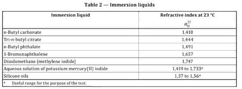
Method B – Immersion Method
Measurement using a microscope and immersion liquids of known refractive index.
For direct measurement of solid plastic specimens, sheets and films, the instrument is primarily based on the principles of Method A.
How Does the Measurement Work?
The measurement is based on the optical interaction between the plastic specimen and a high-refractive-index measuring prism.
A small amount of contacting liquid is placed between the specimen and the main prism to establish proper optical contact.
The optical system illuminates the prism/specimen interface and generates a transition between a bright region and a dark region.
The angular position of this boundary depends on the critical optical condition at the interface and therefore on the refractive index of the specimen.
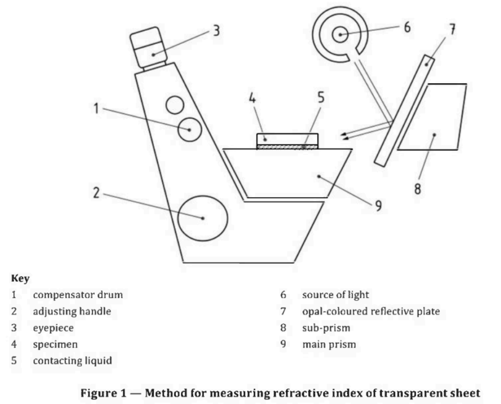
The illustration should show:
- Light source
- Main prism
- Sub-prism
- Plastic specimen
- Contacting liquid
- Optical path
- Reflected/refracted light
- Detection system
Automatic Optical Boundary Detection
In a conventional Abbe refractometer, the operator observes the optical field through an eyepiece and manually aligns the boundary between the bright and dark regions with a reference crosshair.
A digital measurement system can replace this visual operation with an electronic optical detector or imaging sensor.
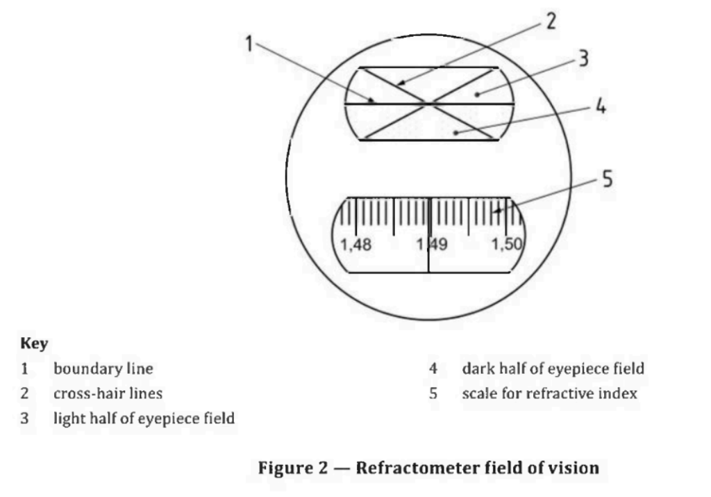
The detector captures the intensity distribution across the optical field. The measurement algorithm determines the precise location of the light/dark transition and converts its position into a refractive-index value using the instrument calibration function.
This architecture can reduce operator dependency and enables automatic digital measurement.
The principle corresponds to the refractometer field-of-view arrangement illustrated in Figure 2 of ISO 489:2022.
Measurement Range
The Abbe refractometer described for Method A covers approximately:
Refractive Index
n = 1.300 to 1.700
Accuracy
±0.001
This range covers many common polymeric materials and makes the system suitable for laboratory and industrial plastics characterization.
Optical Wavelength
Refractive index depends on the wavelength at which the measurement is performed.
ISO 489:2022 refers to the sodium D-line at approximately:
λ = 589 nm
as the reference wavelength.
A modern digital instrument can therefore employ a controlled narrow-band optical source operating near 589 nm to establish a defined measurement wavelength.
This is particularly important when comparing results between different instruments or laboratories.
Precision Temperature Control
Temperature has a direct influence on refractive-index measurement.
For Method A, determination is performed at:
23.0 ± 0.5 °C
Therefore, temperature stability of the specimen and measuring prism is a critical part of the instrument design.
Recommended Temperature-Control Architecture
Temperature Sensor -> Digital Controller -> Heating/Cooling Element -> Measuring Prism
A digital instrument may use:
- Precision temperature sensor
- Closed-loop temperature controller
- Thermoelectric heating/cooling element
- Thermal coupling to the main prism
- Real-time temperature monitoring
The measurement should only be accepted when the prism/specimen assembly has reached the required temperature stability.
Measurement of Transparent Plastic Sheets
For transparent sheet specimens, the sample is placed directly against the measuring prism using a suitable contacting liquid.
The contacting liquid establishes an optically continuous interface between the plastic specimen and the prism.
Recommended cross-sectional arrangement:
Plastic Specimen
↓
Contacting Liquid
↓
Main Measuring Prism
The complete optical diagram should additionally show the illumination source, sub-prism and optical detection path.
The specimen surface contacting the prism should be optically flat and sufficiently well polished to provide reliable optical coupling.
For sheet specimens, ISO 489:2022 recommends a specimen thickness of approximately:
3 to 5 mm
Surface defects, cutting burrs, contamination and poor optical contact can adversely affect the measurement.
Measurement of Thin Plastic Films
The system can also be configured for measurement of very thin polymer films.
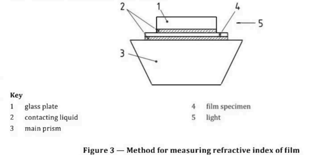
For film measurement, a small amount of contacting liquid is first placed on the main prism.
The film specimen is then positioned over the prism.
A glass plate is placed above the film using an additional layer of contacting liquid.
Recommended cross-section:
Glass Plate
↓
Contacting Liquid
↓
Polymer Film
↓
Contacting Liquid
↓
Main Prism
The arrangement provides optical coupling on both surfaces of the film and facilitates measurement of thin specimens.
ISO 489:2022 indicates that film thickness can be as low as approximately:
2 μm
Air bubbles between the film, liquid, glass and prism should be avoided because they can disturb the optical boundary and reduce measurement reliability.
Contacting Liquid
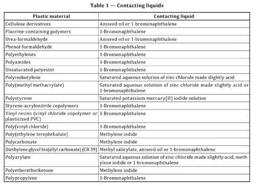
Selection of the contacting liquid is an important part of the measurement.
The liquid should have a higher refractive index than the plastic material being measured.
At the same time, it must not:
- Soften the polymer
- Dissolve the specimen
- Chemically attack the specimen
- Produce an undesirable interaction with the plastic
The liquid provides the optical connection between the specimen and measuring prism.
The appropriate liquid therefore depends on both the expected refractive index and the chemical compatibility of the polymer.
Measurement of Anisotropic Plastics
Many polymer manufacturing processes create molecular orientation within the material.
Examples include:
- Extrusion
- Injection moulding
- Film stretching
- Oriented sheet production
As a result, the refractive index measured in one direction can differ from the refractive index measured in another direction.
ISO 489:2022 therefore includes procedures for measuring anisotropic materials in different specimen orientations.
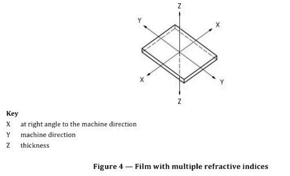
The illustration should show a rectangular polymer specimen with:
X – Direction perpendicular to machine direction
Y – Machine direction
Z – Thickness direction
This diagram should be based conceptually on the orientation system shown in Figure 4 of ISO 489:2022.
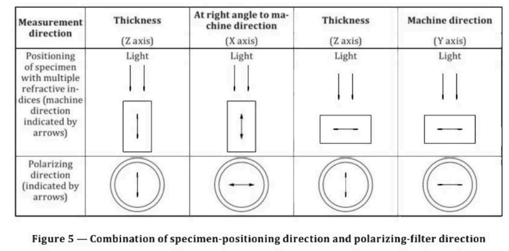
Polarized Measurement
For anisotropic materials, the optical system can additionally incorporate a polarizing filter.
Measurements can then be performed using different combinations of:
- Specimen orientation
- Machine direction
- Transverse direction
- Thickness direction
- Polarization direction
Recommended illustration:
589 nm Light -> Polarizer -> Prism -> Oriented Polymer Specimen -> Detector
The polarization direction should be clearly indicated with arrows.
Such measurements are useful for investigating direction-dependent optical properties produced by polymer processing and molecular orientation.
Measurement of Translucent, Coloured and Opaque Plastics
The ISO 489 procedure is not limited to completely transparent specimens.
Certain:
Translucent – Coloured – Opaque
plastic materials can also be evaluated.
For these specimens, a reflection measurement configuration is used.
Instead of relying on transmitted light through the complete specimen, the optical system evaluates reflected light from the specimen/prism interface.
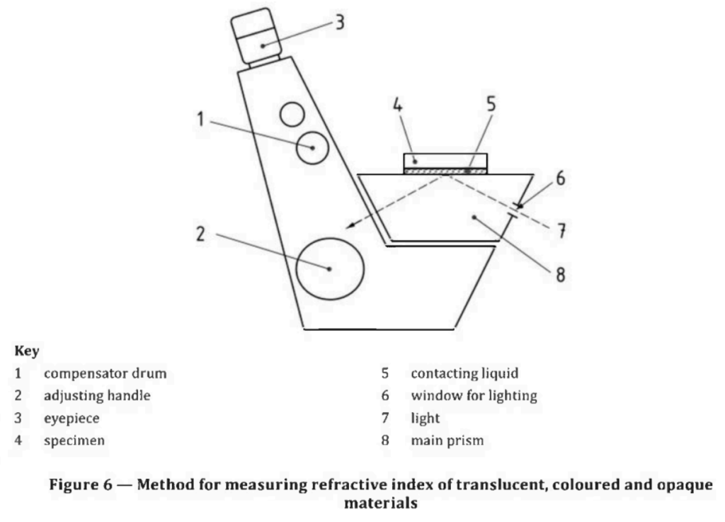
Recommended optical arrangement:
Light Source -> Illumination Window -> Main Prism -> Contacting Liquid -> Opaque Specimen
followed by:
Reflected Light -> Main Prism -> Optical Detection System
The diagram should clearly distinguish the incident light from the reflected measurement light.
This arrangement is conceptually based on the reflection configuration illustrated in Figure 6 of ISO 489:2022.
Sample Preparation
Correct specimen preparation is essential for accurate refractive-index measurement.
For sheet specimens, the surface in contact with the prism should be:
- Optically flat
- Sufficiently polished
- Clean
- Free from cutting burrs
- Free from contamination
The specimen should provide uniform contact with the measuring prism.
Poor surface preparation can produce an unstable or poorly defined optical boundary.
Environmental Conditions
Specimen conditioning is performed according to the conditions referenced in ISO 489:2022 and ISO 291.
The reference atmosphere specified is:
Temperature
23 ± 2 °C
Relative Humidity
50 ± 5 % RH
The measurement equipment should also be operated in a controlled environment to minimize variations caused by external temperature and humidity changes.
Digital Instrument Architecture
A modern refractive-index measurement system based on the ISO 489 Method A principle can integrate the complete measurement process into a digitally controlled platform.
Recommended system diagram:
589 nm Light Source
↓
Illumination Optics
↓
Sub-Prism / Sample Interface
↓
Plastic Specimen
↓
Contacting Liquid
↓
Main Measuring Prism
↓
Optical Detection System
↓
Image / Signal Processing
↓
Boundary Detection Algorithm
↓
Calibration Function
↓
REFRACTIVE INDEX (n)
A separate closed-loop temperature-control system should simultaneously maintain the measuring assembly at the required temperature.
Recommended System Features
A digital refractive-index measurement instrument can include:
- Measurement range approximately 1.300 to 1.700
- Target measurement accuracy of ±0.001
- Optical source near 589 nm
- Precision optical measuring prism
- Digital optical detection
- Automatic light/dark boundary detection
- Closed-loop prism temperature control
- Measurement at 23.0 ± 0.5 °C
- Digital calibration
- Sample identification
- Measurement history
- Test-data storage
- Automatic test-report generation
- USB or network data transfer
- Optional polarization module
- Optional reflection measurement mode
Typical Applications
The system can be used for optical characterization and quality control of:
- Transparent plastic sheets
- Polymer films
- Injection-moulded components
- Extruded plastics
- Oriented polymer films
- Translucent plastics
- Coloured polymers
- Selected opaque plastics
Typical application areas include:
Polymer Laboratories | Plastics Manufacturing | Quality Control | R&D | Material Identification | Incoming Material Inspection
Test Report
For traceable testing according to ISO 489:2022, the measurement report should include relevant information such as:
- Reference to ISO 489:2022
- Complete identification of the tested material
- Measurement method used
- Type of light source
- Measurement wavelength
- Specimen orientation where applicable
- Dispersion information where applicable to Method A
- Immersion liquid where Method B is used
- Measured refractive index
- Any deviation from the specified procedure
- Date of measurement
This provides a structured basis for laboratory documentation, material comparison and quality-control records.