
7 Apparatus
7.1 Testing Machine— The apparatus shall be constructed essentially as shown in Fig. 2 and Fig. 3 and shall consist of the following: suitable base to withstand the impact shock; steel rod impact weight weighing 8 ± 0.2 lb (3.6 ± 0.1 kg);
hardened steel impactors as specified in
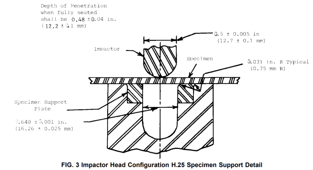
7.1.1; a slotted guide tube 40 in. (1.0 m) in length in which the impact weights slide, having an internal diameter sufficient so that friction does not reduce the weight velocity, and having graduations in inchpound (newton-metre) increments, or multiples thereof. A bracket is used to hold the tube in a vertical position by attaching it to the base and also to hold the hand knob, which is a pivot-arm alignment for the impactor, about 2 in. (50 mm) under the tube. The top edge of the opening in the specimen support plate should be rounded to a 0.031-in. (0.8-mm) radius. Fig. 3 shows the specimen support configuration for this test.
7.1.1 Impactor Configurations:
7.1.1.1 Impactor C.125 shall be constructed, as is shown in Fig. 4, of tough, hardened (Rockwell C 50-55), scratch resistant steel. It should have a conical (40-°) configuration and 0.125-in. (3.18-mm) radius hemispherical tip.
7.1.1.2 Impactor H.25 shall be constructed, as is shown in Fig. 3, of tough, hardened (Rockwell C 50-55) scratch resistant steel. It should have a 0.25-in. (6.35-mm) radius hemispherical tip (see Fig. 3andFig. 4 ).
7.1.1.3 The surface of the impactor head shall be polished free of nicks, scratches, or other surface irregularities.
7.2 Supporting Base—In order to minimize the energy absorption, compression, and deflection of the support the tester shall be firmly fixed to a dense, solid, block or base.
7.2.1 The main body of said block or base shall have maximum dimensions of 16 in. (h)*30 in. (w)*30 in. (d) and shall have a minimum weight of 400 lbs. This block shall be placed at a height that facilitates equipment usage. It is not necessary to bolt blocks or bases of this weight to the floor.
NOTE 3—The required block weight and dimensions conform to commercially available butcher block type tables.
7.2.2 Alternative supporting bases or those lighter than 400 lbs should be bolted to a concrete floor. Mean failure energy comparisons shall be made between these alternative supports and one where the tester is bolted directly to the concrete floor. If mean failure energy differences between the concrete floor and the alternative support are found statistically nonsignificant, use of the lighter support shall be allowed.
7.2.3 Use of rubber mats either under the tester or the supporting base is prohibited.
7.3 Micrometer, for measurement of specimen thickness. It should be accurate to 1 % of the average thickness of specimens used. See Test Methods D 374 for suitable micrometers.
8 Safety Precautions
8.1 Shielding devices shall be provided to protect personnel.
8.2 A tube can contain the impactor head if it rebounds after striking a specimen, or the impactor head may be drilled for a cotterpin to prevent rebound. The cotterpin must be located well above the penetration depth of the impactor head.
10 Test Specimen
10.1 Flat test specimens at least 0.75-in. (19-mm) wide can be tested. The specimens shall be free of obvious imperfections unless they constitute variables under study.
10.2 When the approximate mean failure height for a given sample is known, 20 specimens usually yield sufficiently precise results. If the mean failure height cannot be approximated, six or more specimens should be used to determine the appropriate starting point of the test.
NOTE 4—Specimen quantity, as small as five, often yields sufficiently reliable estimates of the mean failure height. However, the estimated standard deviation will be relatively large.
11 Conditioning
11.1 Unless otherwise specified, condition the test specimens at 73.4 ± 3.6°F (23 ± 2°C) and 50 ± 5 % relative humidity for not less than 40 h prior to test in accordance with Procedure A of Methods D 618. In cases of disagreement, the tolerance shall be ±1.8°F (±1°C) and ±2 % relative humidity.
11.2 Quality Control Tests—Condition the test specimens at 73.4 ± 3.6°F (23 ± 2°C) for 4 h in air.
12 Procedure
12.1 Procedure A:
12.1.1 Measure and record the thickness of each specimen at the anticipated area of impact. Average the values for all specimens in a sample and use this average thickness in calculating normalized mean failure energy.
NOTE 5—When using a large specimen, such as PVC sliding, measure the thickness at five points uniformly across the width of the specimen. Use the average of these five values as the average thickness to calculate the normalized mean failure energy.
12.1.2 Choose a specimen at random from the sample. Determine the order of testing by using a set of random numbers.
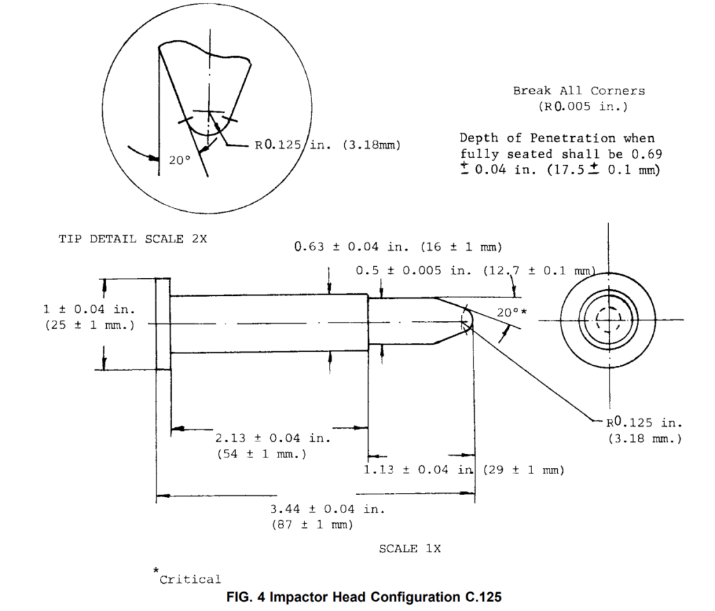
12.1.3 Select the proper impactor-head configuration (C.125 or H.25) specified for the test and install on the apparatus. Adjust the guide arm so that each impactor head is visually centered and achieves the proper depth of penetration. Depth of penetration is the distance the impactor head protrudes into the support plate when properly seated. For the H.25 tup this shall be 0.48 in ± 0.04 in. (1.22 cm ± 0.10 cm) (Fig. 3) and 0.69in. ± 0.04in. (1.75 cm ± 0.10 cm) for the C.125 tup (Fig. 4).
NOTE 6—Centering of Tup- Periodic visual inspection during testing ensures tup is centered.
12.1.4 After raising the weight and impactor foot, place the specimen between the mandrel and the anvil making sure that it lies flat and covers the anvil. The clamping force, when clamping is used, shall be sufficient to prevent motion of the specimen.
12.1.5 Place the impactor foot so that it rests on the specimen.
12.1.6 Raise the weight in the tube to the approximate failure energy value for the specific sample and release it so that the weight drops on the impactor. If the approximate failure energy value for the sample is unknown, run about six impact tests at varying energy levels to bracket the approximate failure energy level before initiating the test series of impacts.
12.1.7 Remove the specimen and examine it to determine whether it has failed. See 3.2.1 for criteria of failure.
12.1.8 If the first impact of the specimen results in failure, decrease the drop height one increment. If the first impact of the specimen does not cause failure, increase the drop height one increment. Then test a second specimen or target point on the specimen.
12.1.9 In this manner, select the impact height for each successive test from the results observed with the specimen just previously tested. The same target point on a specimen shall not be tested more than once.
12.1.10 For best results, the height increment used should be approximately equivalent to s, the estimated standard deviation of the test for that sample. An increment from 0.5 to 2 times s is satisfactory (see 13.6).
12.1.11 Keep a running plot of the data. Use one symbol, such as “X”, to indicate a failure and a different symbol, such as “O”, to indicate a nonfailure at each height level.
12.1.12 For any specimen that gives a break behavior that appears to be an outlier, the conditions of that impact shall be examined. The specimen may be discarded only if a unique cause for the anomaly can be found, such as an internal flaw visible in the broken specimen. Note that break behavior may vary widely within a set of specimens. Data from specimens which show atypical behavior shall not be discarded simply on the basis of such behavior. Refer to Practice E 178 for detailed information on how outliers shall be handled.
12.2 Procedure B:
12.2.1 Test the specimen in the same way as described in Procedure A (12.1.1-12.1.9).
12.2.2 If brittle failure is observed (Fig. 1) at the mean failure height, the mean brittle failure height and mean brittle failure energy are the same as mean failure height and mean failure energy for the specimen.
12.2.3 If ductile breaks are observed (Fig. 1), continue the test by increasing the height by increments, as described in Procedure A, until a brittle failure occurs.
12.2.4 Use one symbol, such as “D”, to indicate ductile break and a different symbol, such as “B”, to indicate brittle failure at each height level.
13 Calculation
13.1 Mean Failure Height (Procedure A)—Calculate the mean failure height from the test data obtained as follows:
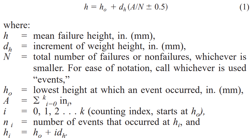
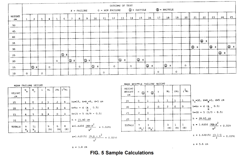
In calculating h, the negative sign is used when the events are failures. The positive sign is used when the events are nonfailures. See the example in Fig. 5.
13.2 Mean Brittle Failure Height (Procedure B)—Calculate the mean brittle failure height using the same formula as in Procedure A. Designations of h and N are different, as follows:
h = mean brittle failure height in. (cm), and
N = total number of brittle failures or ductile breaks, whichever is smaller.
In calculating h, the negative sign is used within the parentheses when the events are brittle failures. The positive sign is used when the events are ductile breaks.
13.3 Mean Failure Energy (Procedure A)—Compute the mean failure energy as follows:

where:
MFE = mean failure energy, in.•lbf (J),
h = mean failure height, in. (cm), and
w = weight, 8 lb (3.6 kg).
13.4 Mean Brittle Failure Energy (Procedure B)—Compute the mean brittle failure energy as follows:
where:
MBFE = mean brittle failure energy, in.•lbf (J),
h = mean brittle failure energy, in. (cm), and
w = weight, 8 lb (3.6 kg).
13.5 Normalized mean failure energy (Procedure A) and normalized mean brittle failure energy (Procedure B) are calculated by dividing the mean energy by the average thickness.
13.6 Estimated Standard Deviation—Calculate the estimated standard deviation from the test data as follows:

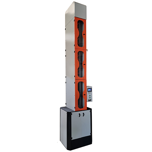
Impact Tester According to ASTM D 4226
- Touch display
- Automatic height adjustment
- Can do defined number of impacts automatically
- Anti rebound system for restricting multi-impacts
- Automatic calculations according to standard
- steel rod impact weight weighing 8 ± 0.2 lb (3.6 ± 0.1 kg)
- Clamp for sample as per ASTM D 4226
- Pneumatic clamp type
- Striker head as per ASTM D 4226
- “Number” & “mass of weights” – “maximum height of impact” are according to customer request