
11 Method E7: Torsion
11.1 Object
This test method is intended to establish the ability of a fibre optic cable to withstand mechanical twisting. The primary purpose of this procedure is to measure any variation in the optical power transmittance of a fibre when the cable is subjected to torsional forces external to the cable sheath. A secondary purpose is to evaluate the possibility of physical damage that may occur as a result of such stresses.
11.2 Sample
The specimen shall be a sample of fibre optic cable having a total length sufficient to permit the appropriate clamping and twisting, and long enough to permit optical transmittance measurements as required by the detail specification.
11.3 Apparatus
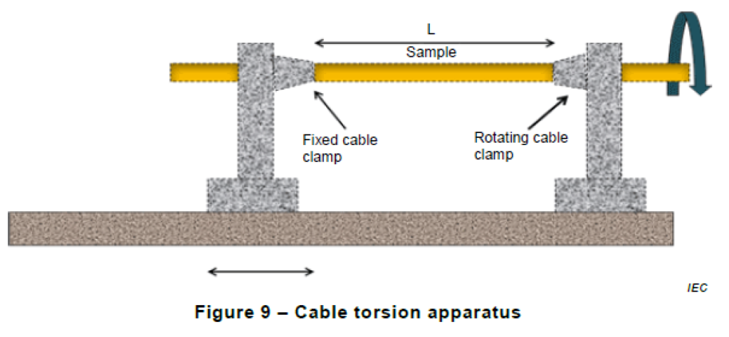
The twisting apparatus consists essentially of two cable gripping devices or clamps, one fixed and one that can rotate, supported as appropriate, the distance between them being adjustable. The rotating clamp is connected to suitable turning equipment (e.g. a torquing lever). Any clamp supports, gripping devices or torquing equipment used shall all be such as to permit access to both ends of the cable specimen for optical testing as may be required. Suitable apparatus is illustrated in Figure 9, Figure 10. and Figure 11.
The cable gripping devices shall be such that
– they may be tightened around the cable sufficiently to prevent movement within the grip,
– the clamps hold the cable firmly in a straight line,
– the clamps induce neither localized twisting damage on the cable caused by the inside
edge of the clamp nor undue localized concentration of pressure on the cable,
– the process of clamping does not induce any significant or accurately measurable attenuation increase (or no more than a negligible increase) in the specimen.
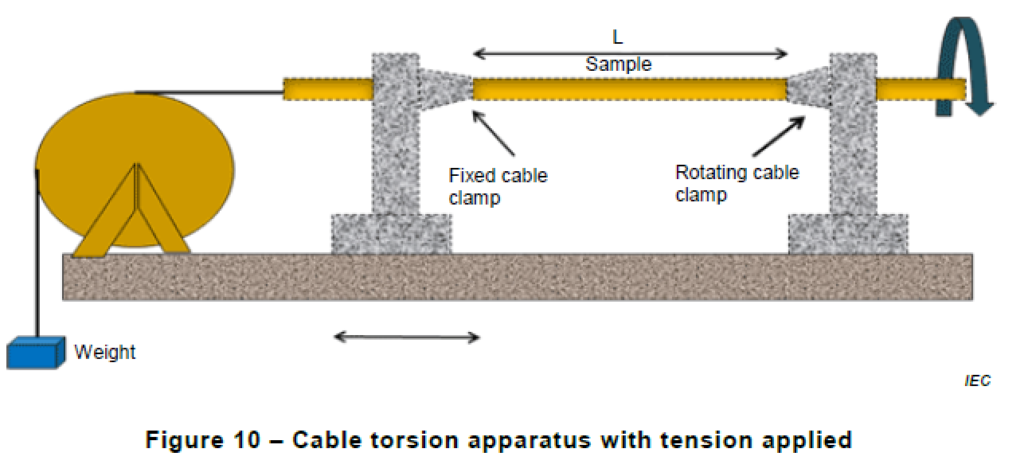
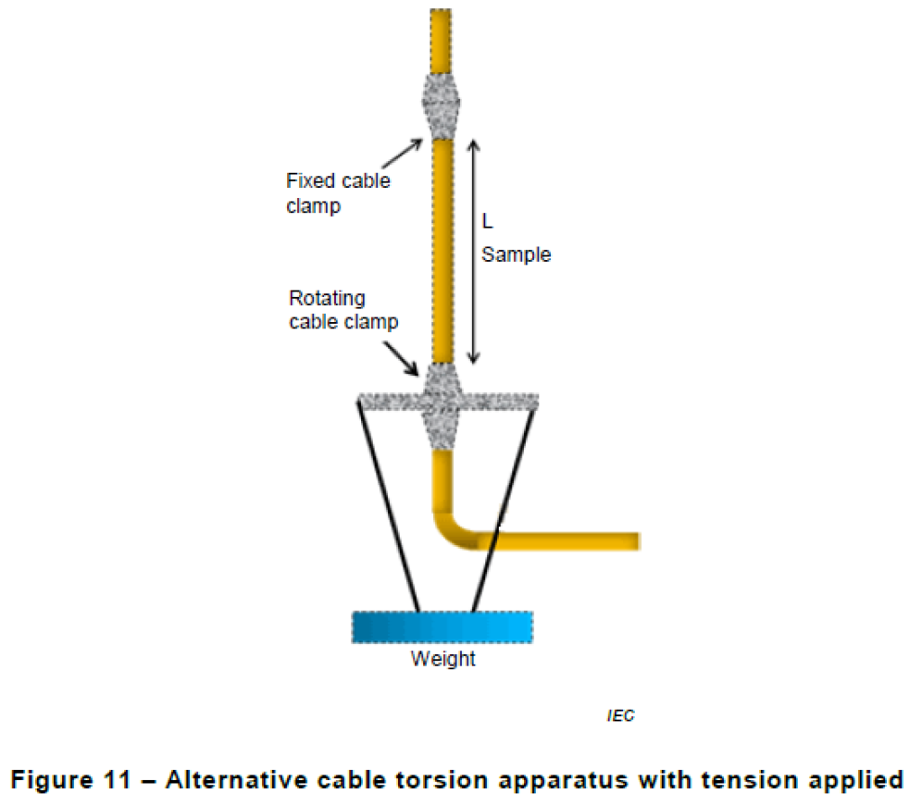
If required by the detail specification and/or to minimize specimen bending from a straight configuration, use weights or an appropriate loading mechanism to apply a tensile load to the cable gripping fixture (see Figure 10. Figure 11). In any case, one end of the gripping fixtures shall be free to move longitudinally to respond to foreshortening of the cable.
The apparatus shall include optical transmittance equipment to measure the change in optical throughput as required in the detail specification, and specified in Method A (transmitted power) of IEC 60793-1-46:2001.
11.4 Procedure
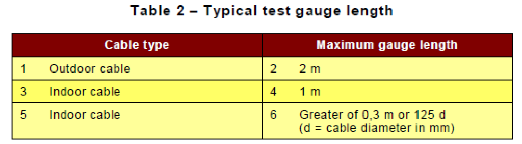
Install the specimen in the test apparatus such that the test length L (see Figure 9, Figure 10 and Figure 11) is as required by Table 2 or by the detail specification.
Take care to insure that no initial stress is applied to the specimen. Except for the necessary twisting operation, take care not to move or disturb the specimen ends throughout the test. Intrinsically torque-resistant cables may need a longer gauge length to be agreed between customer and supplier.
Minimize specimen sag (Figure 9 or Figure 10) or vertical deviation from a straight line (Figure 11) as much as possible.
If change of optical performance is required by the detail specification, measure the unstressed specimen. Compare results with those after clamping to ensure that the clamping has not significantly degraded the cable performance.
If not prohibited by the detail specification, specimen sag or bend may be minimized by supporting the test length or by applying tension to the specimen cable. If required, apply tension as specified in the detail specification to keep the specimen straight.
If a determination of optical transmittance changes is required by the detail specification, measure optical output power for the specimen after clamping and application of tensile load, if any.
Rotate the movable cable clamp as follows:
a) 180° clockwise;
b) return to the starting position;
c) 180° counter-clockwise;
d) return to the starting position.
This total four-part movement constitutes one cycle. Complete each cycle within 1 min maximum, for a total of 10 cycles.
Carry out the acceptance criteria parameters measurements. Allow the specimen to rest for a minimum period of 5 min. If necessary, the sample may be removed from the apparatus for visual examination using normal corrected vision.
11.5 Requirements
The acceptance criteria for the sample under test shall be as stated in the detail specification. Typical failure modes include loss of optical continuity, increase in fibre loss and damage to the cable sheath or core components.
11.6 Details to be specified
The detail specification shall include the following:
a) test length, L, if other than specified herein;
b) any tension which is to be applied, if applicable;
c) number of cycles, if other than specified herein;
d) number of fibres to be monitored for optical transmittance;
e) maximum allowable change in optical transmittance, if required;
f) rotating angle, if other than specified herein;
g) temperature of the specimen, if other than specified herein.
11.7 Details to be reported
The following details shall be reported:
a) number of cycles;
b) cycle time.
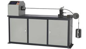
Torsion Tester According to IEC-60794-1-21 Method E7
The Optical Fiber Cable Torsion Testing Machine is used to determine the ability of optical fiber cable to withstand mechanical twisting.
· Touch screen 7”
· Max distance between grips: 1000mm
· Torsion angle: 90, 180, 360 degrees
· Twisting cycles: up to 9999
· Frequency of loading: 50-30 cycles per minute
· Mass of weights: 1-10kg