
4 Details of test enclosure
The equipment shall comprise a cubic enclosure with inside dimensions of 3 000 mm ± 30 mm and constructed of a suitable material fixed on to a steel angle frame. One side shall have a door, with a glass inspection window. Transparent sealed windows (minimum size 100 mm × 100 mm) shall be provided on two opposite sides to permit the transmission of a beam of light from the horizontal photometric system. The distance from the floor to the centre of these windows shall be 2 150 mm ± 100 mm (see Figure 1 for plan view).
The walls of the enclosure shall include orifices at ground level (i.e. not greater than 100 mm above the level of the chamber floor) for the passage of cables, etc., and to permit the enclosure to be at atmospheric pressure.
No orifice shall be directly behind the fire source or on the same wall. A minimum of two orifices shall be provided and the total area of the orifices open during the test shall be 50 cm2 ± 10 cm2.
NOTE 1 Two orifices, each with an area of 25 cm² ± 5 cm², and located on two opposite walls, one under the light source and one under the receiver have been found to be suitable.
The ambient temperature outside the enclosure shall be 20 °C ± 10 °C and the enclosure shall not be directly exposed to sunlight or extreme climatic changes.
NOTE 2 It should normally be possible to extract fumes from the enclosure after each test through a duct
complete with valve which should be closed during the test. The duct may include a fan to increase the rate of extraction. It is recommended that the door of the enclosure be opened to assist the extraction process. A draught screen, 1 500 mm ± 50 mm long and 1 000 mm ± 50 mm high, shall be placed in the enclosure, at the position shown in Figure 1. It shall abut on the back wall (with a maximum gap of 10 mm) at a point 750 mm ± 25 mm from the side wall, and shall be curved to intersect the centre line of the enclosure at a point 1 400 mm ± 25 mm from the point of abutment.
5 Photometric system
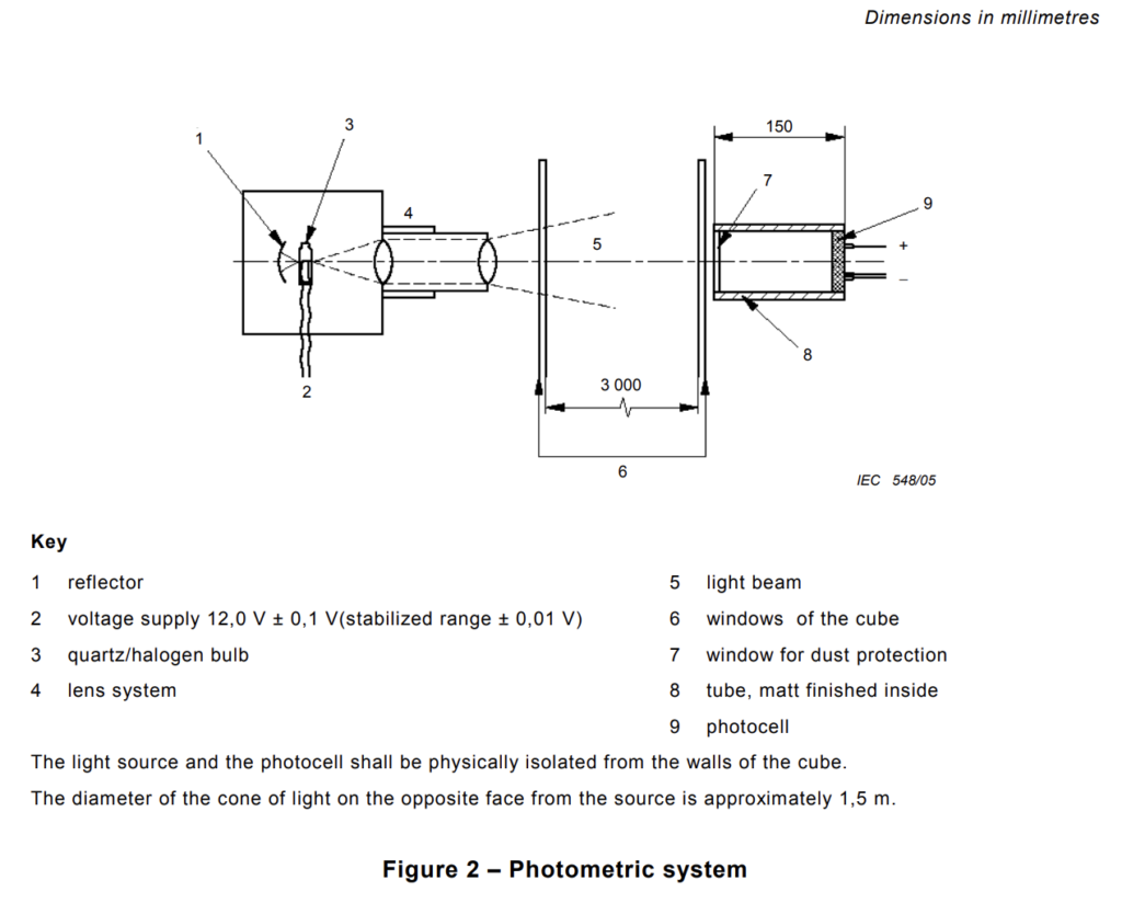
5.1 The photometric system is illustrated in Figure 2. The light source and the receiver shall be placed externally in the centre of both windows in the two opposite walls of the cube without making physical contact. The light beam shall traverse the cube through the glass windows in the side walls.
5.2 The light source shall be a halogen lamp with a tungsten filament with a clear quartz bulb
having the following characteristics:
nominal power: 100 W;
nominal voltage: 12 V d.c.;
nominal luminous flux: 2 000 lm to 3 000 lm;
nominal colour temperature: 2 800 K to 3 200 K.
The bulb shall be supplied with a voltage of 12,0 V ± 0,1 V (mean value). During the test, the voltage shall be stabilized to a range of ± 0,01 V (see A.2c) for additional guidance.) The lamp shall be mounted in a housing and the beam adjusted by a lens system to give an evenly illuminated circular area of 1,5 m ± 0,1 m diameter on the interior of the opposite wall.
5.3 The receptor photocell shall be of the selenium or silicon type with a spectral response matching the International Commission on Illumination (CIE) photopic observer (equivalent to the human eye). The photocell shall be mounted at the end of 150 mm ± 10 mm tube with a dust protection window at the other end. The inside of the tube shall be matt black to prevent reflections. The photocell shall be connected to a potentiometric recorder to produce a linear proportional output. The cell shall be resistance-loaded to operate in its linear range and the input impedance of the recorder shall be at least 104 times greater than the load resistance of the cell which shall not exceed 100 Ω.
5.4 The photometric system shall be energized before the blank test. When stability has been attained, the zero and full scale reading of the recorder shall be adjusted for light on the detector corresponding to 0 % (absence of light) and 100 % luminous transmission.
NOTE 1 Periodically, for example at the beginning of a test series, the performance of the photocell should be verified by placing standard neutral density filters in the light beam. It is essential that these filters cover the entire optical port of the photocell and the values of transmittance measured by the photocell give a value of parameter A within ± 5 % of the calibrated value of the filter. The filters should also permit the verification of the linearity of response of the detector which should be proportional to the transmittance of light in the range used.
NOTE 2 Most neutral density filters are designated according to a parameter defined as absorbance which is the same as the parameter A defined in 10.5 which may be used to convert measured transmittance.
6 Standard fire source
The standard fire source shall be 1,00 l ± 0,01 l of alcohol having the following composition by volume:
ethanol: 90 % ± 1 %
methanol: 4 % ± 1 %
water: 6 % ± 1 %.
When a denaturing agent is added to the alcohol, it shall have no effect on the smoke emission of any cable under test.
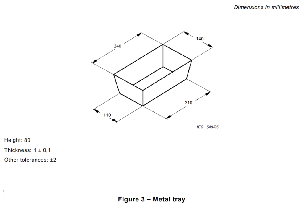
The alcohol shall be contained in a tray made from galvanized or stainless steel with jointed sealed edges, a trapezoidal trunk section and the following interior dimensions (see Figure 3):
bottom base: (210 ± 2) mm × (110 ± 2) mm;
top base: (240 ± 2) mm × (140 ± 2) mm;
height: (80 ± 2) mm;
thickness of tray: (1,0 ± 0,1) mm.
The tray shall be supported at a height of 100 mm ± 10 mm from the floor on an open sided framework to permit air circulation around and beneath the tray.
7 Smoke mixing
In order to ensure uniform distribution of the smoke, a table-type fan shall be placed on the floor of the cube as shown in Figure 1, the fan axis being between 200 mm and 300 mm from the floor and the distance from the wall being 500 mm ± 50 mm. The fan shall have a blade sweep of 300 mm ± 60 mm and a flow rate of 7 m3/min to 15 m3/min. Air shall then be blown horizontally by the fan during the tests but the ignition source shall be protected by the screen as shown.
NOTE Suitable fans may be found by reference to IEC 60879: 1986.
8 Blank test
8.1 Purpose
The purpose of the blank test is to condition the interior of the cube to the specified temperature range, when necessary, prior to carrying out tests.
8.2 Procedure
8.2.1 Burn approximately 1 l of alcohol as detailed in Clause 6, in order to preheat the test enclosure.
8.2.2 Purge the inside of the cube of all combustion products by operating the extraction system.
9 Qualification of test apparatus
In order to ensure that the combination of the test cube and the optical system produce results consistent with other test cubes when identical cables are burnt under the same conditions, the test apparatus shall be subject to qualification. Qualification shall be achieved by carrying out the qualification burning test (see Clause 10). The test apparatus shall meet the stated requirements.
10 Qualification burning test
10.1 Purpose
The purpose of the qualification burning test is to verify that the smoke produced in the cube gives AC values within the limits quoted in 10.6 for both of the alcohol/ toluene fire sources described in 10.3.
10.2 Preparation of cube
Clean the windows of the photometric system to regain 100 % transmission after stabilization of the voltage.
Immediately before commencing the test, the temperature inside the cube shall be within the range 25 °C ± 5 °C when measured at the internal door surface at a height of 1,5 m to 2,0 m and a minimum of 0,2 m from the walls. If necessary, carry out a blank test in order to condition the interior of the cube to the specific temperature range.
10.3 Qualification fire sources
The two mixtures shall be prepared by measuring the required quantity of toluene, 40 ml for a) or 100 ml for b), into a 1,0 l volumetric flask using a pipette and adding alcohol up to the 1,0 l calibration mark.
NOTE PA toluene has a purity greater than 99,5 %.
The mixtures shall be contained in a tray as described in Clause 6.
10.4 Test procedure
Burn 1 l ± 0,01 l of the test solutions specified in 10.3. Record the minimum of the measured transmittance level It during the test.
10.5 Calculation
Calculate the measured parameter (Am) as follows:
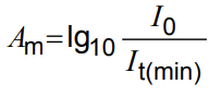
“where I0 is the initial transmittance level of incident light and It(min) is the minimum of the measured transmittance level during the qualification test.”
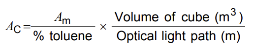
Calculate the standard parameter (AC):
10.6 Requirements
The calculated values of AC shall fall between the following limits:
4 % toluene: 0,18 m2 to 0,26 m2;
10 % toluene: 0,80 m2 to 1,20 m2.
Annex A
(informative)
Guidance notes
A.1 The chamber environment and ignition source
a) Early test chamber requirements included a specification for the walls to ensure that the heat loss was uniform, for example similar to 2 mm of steel. This has lost its significance now that the toluene verification procedure has been introduced.
b) It is important to provide for pressure equalization and suitable arrangements should be made.
c) Condensation at the lower end of the operating temperature range can cause anomalous results; for example, 15 °C is unacceptable, 18 °C is the minimum, and 20 °C (as specified) the safe minimum.
d) The tray containing the toluene mixture should be raised above floor level to permit air circulation.
e) The water content in the alcohol can significantly affect values of smoke production. Thus, for the calibration test it is important to take into account the water content in the ethanol to ensure that the percentage is within the defined limits, and to carry out the test within 2 h of mixing.
f) The fan throughput should either be certified or checked by a suitable means, for example using an anemometer at the end of a tube having a diameter of the blade sweep and of sufficient length, i.e. 1,0 m.
A.2 Optical system
a) There is no reason to verify the output of the light source as the actual power plays no part in the accuracy of the test and the bulbs may be operated until failure; this is because all measurements of lt are relative to the initial I0.
b) The effect of the colour temperature and the emissivity of the bulbs at various wavelengths are also minimal, particularly when the fact that the receptor is weighted for human eye response is considered. Loss of some intensity at the “blue” end or gain of intensity at the “red” end of the spectrum due to the normal ageing of these bulbs, is irrelevant because these wavelengths contribute very little when “weighted” by the receptor.
c) The above effects also make the precision of the initial d.c. voltage applied across the bulb of little importance. Thus, if 12,1 V or 11,9 V is used instead of 12,0 V d.c. the effect is merely to change the absolute intensity and also to alter the colour temperature. These two effects, as stated above, have minimal effects on the results. The crucial feature of the
voltage applied to the bulb is that it be kept stable to a very close tolerance. Thus, it is ideal to maintain the voltage at ±0,01 V for the duration of the test but it is largely irrelevant whether the absolute voltage is stablized at 11,9 V, 12,0 V or 12,1 V.
d) The receptor cell is designed to operate well within its linear range. For example, the selenium cell Megatron MF45 becomes non-linear at an output voltage of 40 mV. The actual output under the illumination conditions in the cube is about 3,5 mV.
e) The use of standard neutral density filters is needed to determine that the relative response of the system stays in the same order on a month-by-month basis.
Before the calibration of the photometric system, it is desirable that the filters are calibrated to confirm the specified nominal values.
When any change is made to the intensity of the light beam after calibration, confirmation of linear response to the filters should be obtained, for example by using a suitable light meter.
f) The relative nature of the I0/It measurement means that, in theory, there is little or no need to clean the windows of the optical system prior to use. In practice, there is a reason for cleaning after each test. The reason is related to the reflection from the detector window which varies considerably with small amounts of deposited smoke. It is possible to have more light transmitted after some smoke has been deposited because of the reduction in reflection quality of the surface. Cleaning the windows after each test or series of tests ensures more consistency.
Alternatively, a continuous flow of air having a maximum flow rate of 2 l/min may be permitted to sweep the window surfaces during the test.
g) The light source is set up to give a diffuse and defocused area for two reasons. One has already been described, but the main one is to allow the photocell to sample a small part of a large, evenly illuminated area. This will prevent the situation where, for example, a bright patch exists just outside of the area monitored by the cell which then, when some smoke is produced, scatters light into the cell giving a false reading.
For this reason, the diameter of the light area should not be too small and should conform to the specified limits.
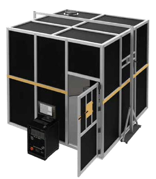
Smoke density Chamber According to IEC 61034-1
- Width x depth x height: 3320 x 3320 x 3250 mm
- Weight: approx. 1000 kg
- Exhaust duct with extraction DN 40
- Power supply 230 VAC 50/60 Hz
- Cable and line sections of 1000 mm in length are placed over a trough filled with an alcohol mixture. The alcohol is then ignited and the smoke is mixed with the combustion chamber air using a fan. A photometric system measures the smoke obscuration.
- Combustion chamber 27 m3 with door and windshield (Aluminum profile frame, aluminum sheet wall panels, aluminum checker plate floor)
- specimen rack, stainless steel
- Trough, stainless steel
- Fan
- Light measuring system (halogen lamp 100W / 3600 lm / 3200 K, silicium photo cell/ output voltage 40 mV non-linear / effective output voltage under test room conditions 3,5 mV.)
- Control cabinet, integrated PC with software