
1 Scope.
1.1 This method covers the determination of the energy required to cause the failure of plastic
samples at low temperature by free-falling darts.
1.2 Four test procedures are included.
1.2.1 Procedure A requires a 10 lb. (4.536 kg) dart.
1.2.2 Procedure B requires a 15 lb. (6.804 kg) dart.
1.2.3 Procedure C requires a 20 lb. (9.072 kg) dart.
1.2.4 Procedure D requires a 30 lb. (13.61 kg) dart.
1.3 Two types of failure are described.
1.3.1 Ductile failure – occurs when dart elongates the sample and punctures a hole in the test sample.
1.3.2 Brittle failure – occurs when sample fails in a brittle manner, shattering or splitting into two or more pieces; or when the impacted areas break loose without elongation.
1.4 Sample preparation for impact data shown in ARM International’s Listing of Resin Properties.
1.4.1 Test specimens to be impacted are to be from a rotationally molded part. The falling dart should impact the surface of the part that was in contact with the mold when it was molded.
1.5 This test involves heavy weights and falling objects, cold temperatures, loud noise and a risk of flying debris. Care should be taken to wear proper personal protective equipment such as safety shoes, safety glasses or goggles, hearing protection and gloves.
2 Summary of Method.
2.1 Each procedure establishes the height of a specific dart that will cause 50% of the specimens to fail. Procedures A, B, and C differ only with respect to dart weights while Procedure D differs with respect to both dart the weight and geometry of the tup.
2.2 The technique used is commonly called the Bruceton Staircase Method or the Up-andDown Method. Testing is concentrated near the mean, reducing the number of specimens required to obtain a reasonably precise estimate of it.
2.3 Since the 30 lb. (13.61 kg) dart has a tup of different geometry, the absolute values of impacts cannot be compared to those obtained with the other darts. In addition, as the velocity of the falling dart will be different for all of the darts, only values of different materials using the same dart can be compared. Note that the report should document the actual dart used (i.e. 10 lb., 15 lb., 20 lb., or 30 lb.).
3 Significance.
The test conditions of procedure A are the same as procedures B & C but differ in dart weight, and they serve only as an indication of low temperature serviceability without direct correlation to engineering data for use in design.
3.1 The main limitation of procedure A is that with the fixed dart weight and a maximum drop height, sufficient energy for failure may not be present to cause failure by any mode.
3.2 Procedures B & C allow for a 50 % and a 100% increase in impact by virtue of the greater dart weight. Procedure D allows for even higher impacts by virtue of the greater dart weight and more severe dart tip/tup geometry. The logical extension is that dart weight can be increased or drop height increased to induce failure, within limits of physical space.
3.2.1 The dart design in all procedures is intended to give the greatest stress concentration in the fastest time so that variation of thickness on tough materials still results in one mode of failure or the other.
3.3 Numerical data obtained by one procedure cannot be interchanged with that from another procedure due to the different dart velocities and dart geometry. However, the mode of failure induced by procedures A, B, C or D can be a useful indicator of “properly processed samples”.
3.3.1 For Polyethylene, a ductile failure is the failure desired mode that generally occurs on properly processed samples.
3.3.2 For Polyethylene, a brittle failure or failure by shattering, generally indicate that the optimum properties have not been obtained by the processing parameters used.
3.4 The height of the tester can be varied to fit the individual requirements of user space; however, maximum impact height of 10 ft. is to be used. Procedures A, B and C make it possible to select a dart weight that in most cases will cause failure at the mid-range of the tester. This will help reduce any effect of velocity on the results, but not negate it. Procedure D is the most severe test and the dart tip will effect will be the overriding factor rather than the velocity effect.
3.5 The specimens should be as nearly flat as possible and unrestrained.
3.6 The results obtained are influenced by the quality of the material of the specimen. Specimens with surface flaws or imperfections in or on either surface should be avoided.
3.7 When comparing samples of varied thickness, impact resistance cannot be normalized for average specimen thickness, even if the surface conditions of specimens are roughly equivalent.
3.8 All samples should be aged consistent with equilibration of the test temperature throughout the part. 3.9 Rotationally molded samples are placed in the sample holder such that the dart contacts the surface that was in contact with the mold when molded. The inside surface of the sample is placed down.
4 Definitions.
4.1 Failures
4.1.1 Ductile – signified by penetration of the dart though the specimen leaving a hole with stringy fibers at point of failure rather than cracking outwardly from point of failure. The area under the dart has elongated and thinned at the point of failure.
4.1.2 Brittle – signified by the part physically coming apart or cracking at the point of impact. Sample has no or very little elongation.
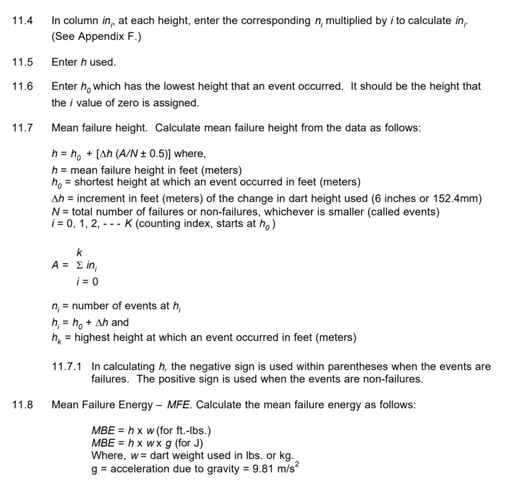
4.2 Drop height – dimension between impact tip of dart and surface of sample to be tested. (See Appendix A)
4.3 Dart and Tup
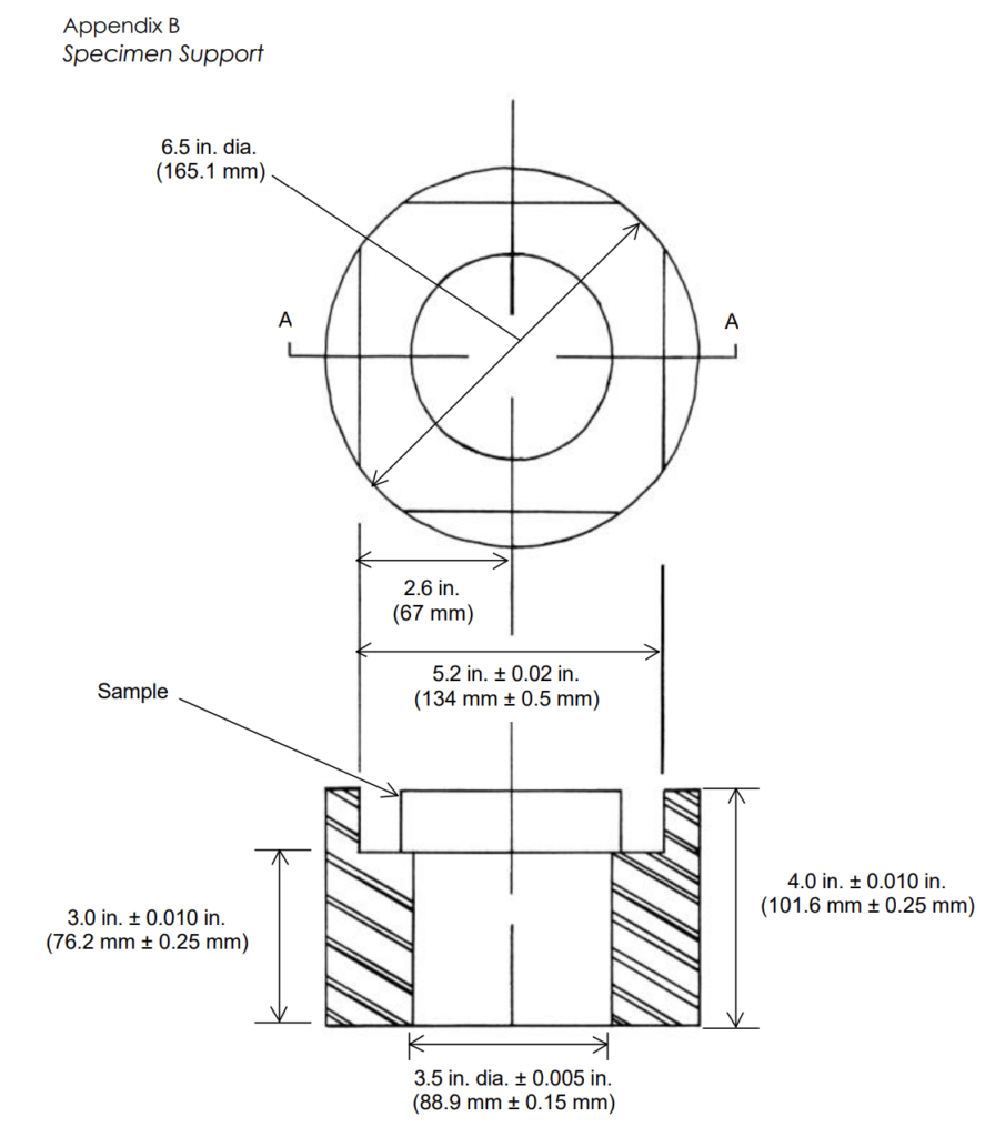
4.3.1 Dart – defined as the entire falling apparatus of given total weight depending on procedure. The dart is comprised of both the tup portion and larger diameter solid mass portion whose length is cut to meet the weight tolerance.
4.3.2 Tup – defined as the 1.0 inch by 4.5 inch (25.4 mm by 114.3 mm) or 0.5 inch by 4.0 inch (12.7 mm by 101.6 mm) hemispherical ended portion of the dart that strikes the specimen.
5 Apparatus.
5.1 Testing machine – constructed as shown in Appendix A.
5.1.1 Procedure A – 10 lb. (4.536 kg) dart as Appendix C.
5.1.2 Procedure B – 15 lb. (6.804 kg) dart as Appendix C.
5.1.3 Procedure C – 20 lb. (9.072 kg) dart as Appendix C.
5.1.4 Procedure D – 30 lb. (13.61 kg) dart as Appendix D.
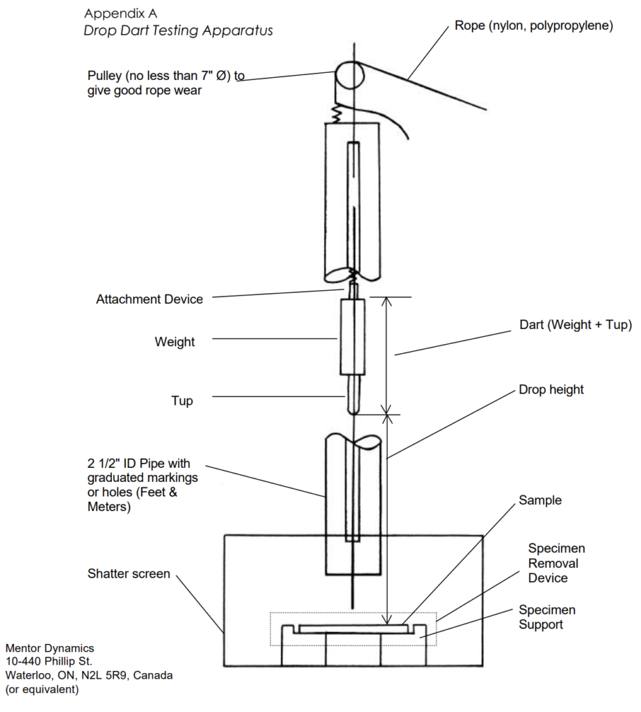
5.2 Specimen support as described in Appendix B.
5.3 Micrometer, for measurement of specimen thickness.
6 Safety Precautions.
6.1 A shield cage should surround the sample and holder and extend above the drop guide
tube shown in Appendix A.
6.2 A cushion of plastic should be inside the sample support to prevent damage to the dart tip
when the dart penetrates a sample.
6.3 All specimens should be handled with tongs or gloves.
6.4 Hearing protection should be worn due to the loud noise generated when the falling dart
strikes the specimen.
7 Sampling.
7.1 Test specimens should be representative of the part under study.
7.2 Test specimens for the ARM International Listing of Resin Properties should be 0.125″ (3.17 mm) and 0.250 inch (6.34 mm) thick. For the ARM International Listing of Resin Properties, the specimen thickness should have a maximum variation of ±10% for 0.125″
(3.17 mm) thick specimens and ±5% for 0.250″ (6.34 mm) thick specimens. Note that Procedure D is typically used for specimens that are greater than 0.4″ (10.2 mm) thick.
8 Test Specimens.
8.1 Test specimens should be obtained from rotationally molded parts.
8.2 Test specimens should be as flat as possible and be free of surface imperfections that would otherwise negate the test.
8.3 Measure part size for 5.0 x 5.0 ± 0.08 in. (127.0 x 127.0 ± 2 mm). This will ensure loose fit in the sample holder.
8.4 Measure and record thickness of each specimen in the area of impact. Note that parts of similar thickness (i.e. within the thickness range criteria) and tested using the same dart can be easily compared.
8.5 Record the specimen thickness on the mold side of the specimen.
9 Conditioning.
9.1 Test specimens should be conditioned to reach uniform chilling of the specimen crosssection to not less than -40F ± 3.5F (-40C ± 2C). Practical experience shows that specimens exposed to -40F / -40C with full surface circulation reach uniform chilling/equilibrium in as little as two hours. Practical experience shows that stacked test specimens exposed to -40F / -40C with limited circulation require much longer exposure time to reach uniform chilling/equilibrium, even greater than 24 hours depending on stack
configuration.
9.2 Unless otherwise specified, the test specimen should be conditioned in an air circulation freezer or cold box for no less than two hours at -40F ± 3.5F (-40C ± 2C) prior to test.
10. Procedure.
10.1 Raise the 10 lb., 15 lb., 20 lb. or 30 lb. dart (4.536 kg, 6.804 kg, 9.072 kg or 13.61 kg dart) to the height expected to cause half of the test specimens to fail. Record the height value.
10.2 Remove the test specimen from the cold storage service using tongs or gloves and place it on the test holder with the surface from the inside of part down and the marked surface up. Ensure that it is centered in the specimen holder.
10.3 Release the dart within 30 seconds of removal from the freezer/placing the test specimen on the test holder.
10.4 Observe and record pass or fail. The specimen is considered to pass if the surface of impact would not leak water if in a container. (No visible hole in the slab sample). Permanent deformation is not a failure. The depth and area of the depression can indicate nearness to failure.
10.5 If the first specimen fails, lower the dropping height by a Dh of usually 6 inches (152.4mm). Repeat test. Continue decreasing height by the same increment until part passes. If first specimen does not fail, increase the drop height 6 inches (152.4mm) and repeat test. Continue increasing the drop height by same increment until failure occurs. If no failure occurs before 75% of the tester height is reached, stop testing and change to a heavier dart. Discard data obtained to this point and start again. Each impact should be on a fresh test specimen.
10.6 This technique allows one to determine the total dart height for each test from the previously tested specimen. The impact test can be performed on a specimen only once.
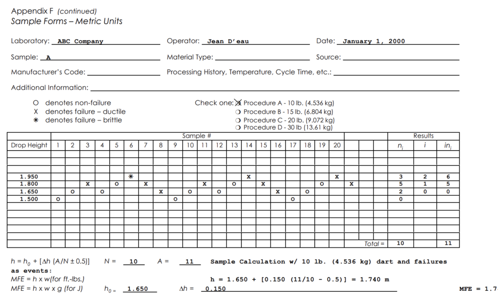
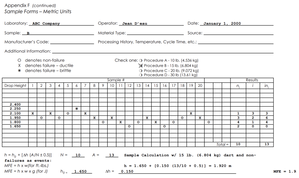
10.7 Use a chart for each specimen as shown in Appendix E. Place a legend on the record to show what symbol represents pass and fail. (Note: Letters such as O for pass and X for Ductile Failure and an * for Brittle Failure clarifies the outcome of each test.)
10.8 Each chart should include as much information on specimen history as possible, such as processing temperature, cycle time, conditioning time, and aging time (length of time since molding).
10.9 For best results, test 20 samples and then count the total number of N (events). This number may be non-failures or failures, whichever is less. N should be 10. If N<10, continue testing until N=10, then stop testing.
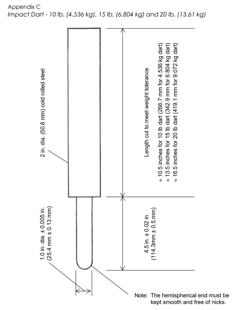
11 Calculations.
11.1 On the data form (Appendix E), record under ni the total number of events (number of failures or non-failures, whichever is less) at each drop height. (See Appendix E.)
11.2 In column i, enter integers 0, 1, 2, etc., for each ni entered. Put 0 for the lowest dart height at which an ni value has been entered, 1 for the next higher dart height, etc.
11.3 Add the ni column. It should always equal 10 if the procedure is followed exactly. The total of the ni column is N.
12 Report.
12.1 The report will contain the following:
12.1.1 Complete identification of sample tested, including material type, source, manufacturers code, form dimensions, history of processing (i.e., time, temperature, and any visual observations concerning the part, bubbles, scratches, etc.)
12.1.2 Method of preparation of specimen.
12.1.3 Mean failure height.
12.1.4 Dart used 10 lb., 15 lb., 20 lb., or 30 lb. (4.536 kg, 6.3804 kg, 9.072 kg or 13.61 kg).
12.1.5 Specimen thickness tested averages and range.
12.1.6 Number of specimens used for determination of mean failure height.
12.1.7 Mean failure energy.
12.1.8 Any variations from the procedure recommended.
12.1.9 Types of failure.
12.1.10 Date of test and operator.

Impact Tester According ARM
- Steel guide with inner diameter according to the standard
- Including weights for Procedure A – 10 lb. (4.536 kg) dart as Appendix C // Procedure B – 15 lb. (6.804 kg) dart as Appendix C // Procedure C – 20 lb. (9.072 kg) dart as Appendix C // Procedure D – 30 lb. (13.61 kg) dart as Appendix D.
- Sample holder suitable for 127.0 x 127.0 ± 2 mm sample piece (According to appendix B)
- Customers also need a deep freeze. in case of need, it will be added to the quotation
- Safety pleaxi-glass door for sample holder
- Guide length of 2 m
- Includes a leveling device
- Graduated rod for easy height adjustment
- Rigid base for sample placement
- Hemispherical impact head (According to Appendix C & D)
- Release of weight is manual
- Easy adjustment of mass drop height