
4 Apparatus
4.1 Apparatus for procedure A
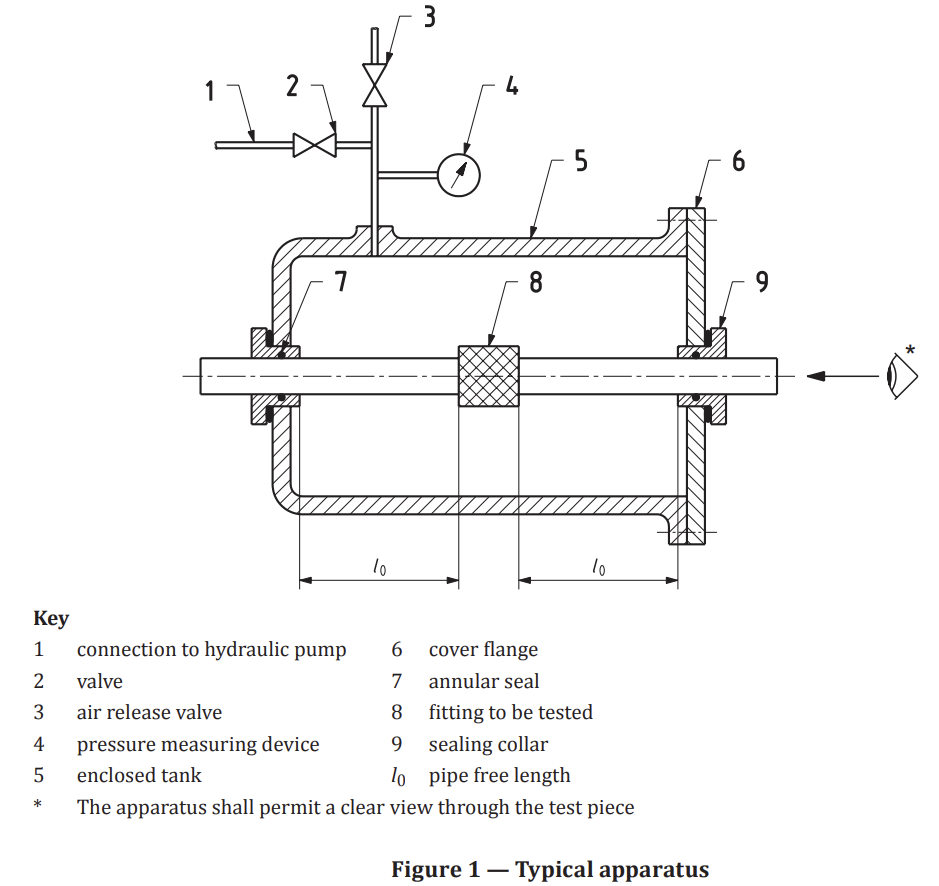
4.1.1 A suitable apparatus for procedure A is shown in Figure 1.
4.1.2 Enclosed tank, capable of being used at the appropriate test pressure and receiving the test
specimen. The ends of the test specimen shall pass through the walls of the tank, so that the inside of the
pipe is open to the atmosphere and the connecting pipes are in axial alignment. The assembly shall be
arranged so as to enable any leakage to be detected within the test specimen.
4.1.3 Pressure source, connected to the tank and capable of raising and maintaining the specified
water pressure with an accuracy of ±0,05 bar.
4.1.4 Pressure measuring device, capable of checking conformity of the test pressure.
4.1.5 Temperature control system, capable of maintaining the temperature of the pressurized water
in the tank at the specified temperature, T, with an accuracy of ±2 °C.
4.2 Apparatus for procedure B
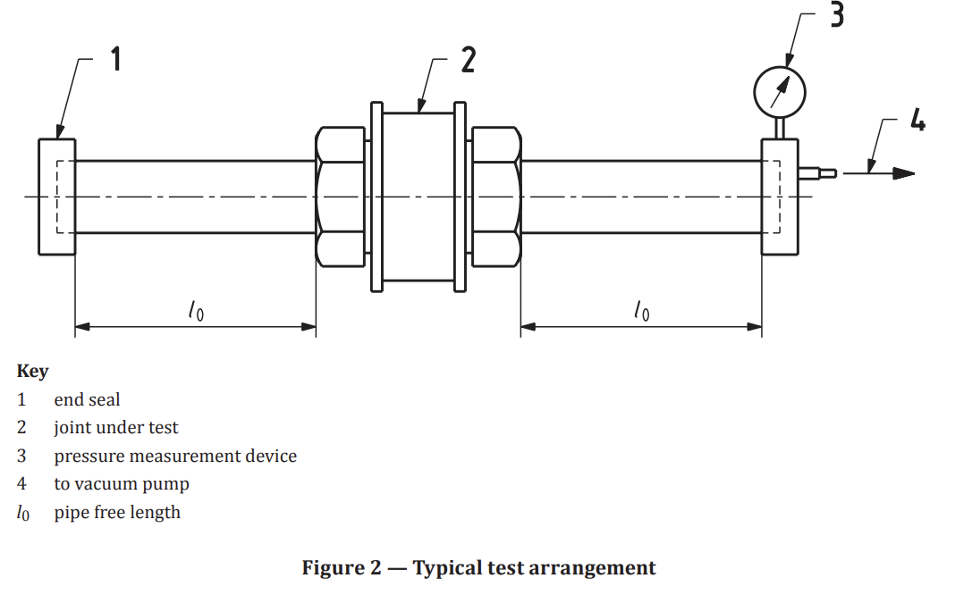
4.2.1 A typical test arrangement for Procedure B is shown in Figure 2.
4.2.2 Vacuum source (pump), capable of producing in the test piece the partial vacuum specified in
the referring standard.
4.2.3 Vacuum pressure measurement device, capable of measuring the pressure in the test piece
with an accuracy of ±0,01 bar.
4.2.4 Shut-off valve, to isolate the test piece from the vacuum source.
4.2.5 Thermometer(s), capable of checking conformity to the specified test temperature.
4.2.6 End-sealing device, of appropriate size and sealing method for sealing the non-jointed end of the
test piece. The device shall be restrained in a manner that does not exert longitudinal forces on the joints.
5 Test pieces
The test specimen shall consist of one or more fittings and two or more pieces of plastic pressure pipe of
the size and quality for which the fitting is designed. The fittings and pipes shall not be tested until 24 h
after their production. For practical reasons, the manufacturer may wait for a shorter period of time
before testing. In case of dispute, a duration of 24 h shall apply.
In case of using procedure B, the test piece shall be connected to the vacuum source (pump) via a line
with a shut-off valve. The vacuum pressure measurement device shall be connected between the shutoff valve and the test piece.
The assembly of the joint should be carried out in accordance with the manufacturer’s instructions.
The mean outside diameter, dem, of the pipe should preferably conform to the minimum specified value,
and the fitting dimensions (mean inside diameter, dim) should preferably conform to the maximum
values stated by the manufacturer, in order to have dimensions as close as possible to the extreme limits
of their relevant tolerances.
6 Procedure A: Pressure outside
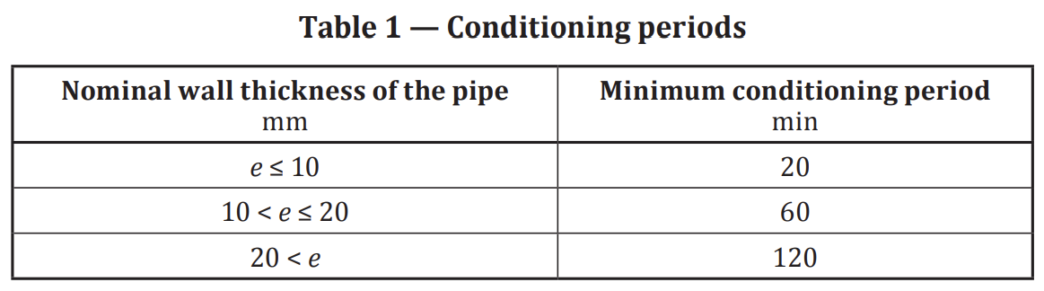
6.1 Secure the test specimen in the water tank. Fill the tank with water at the specified temperature, and
that variations in the test temperature do not exceed ±2 °C. Minimum conditioning times are given in Table 1.
6.2 Remove any condensation from the inside of the test specimen. Wait for 10 min and ensure that the
inside of the test specimen is completely dry.
6.3 After conditioning, progressively and smoothly apply a first test pressure, p1, in the shortest time
practicable for at least 1 h and then smoothly increase the pressure without shock to the second level, p2.
Maintain the test pressure, p2, for a further period of at least 1 h. The test starts on achieving the required
test pressures.
6.4 Maintain a constant reading on the pressure measuring device. Inspect the inside surface of the
test piece for leakage and record any signs of leakage observed, and the pressure at which leakage occurs, while the joint is subjected to external pressure.
7 Procedure B: Vacuum inside
7.1 Minimum conditioning times are given in Table 2.
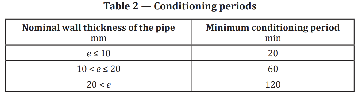
7.2 Ensure that during the procedure, the test temperature is maintained at the specified temperature
and that variations in the test temperature do not exceed ±2 °C.
7.3 Evacuate the test piece to the test pressure specified in the referring standard. Record the time
when the test pressure is achieved and close the shut-off valve.
7.4 Record the increase of pressure, if any, in the test piece until either the test period specified in the
referring standard has elapsed or prior failure of the test piece as indicated be an increase of internal pressure.
8 Test report
The test report shall include the following information:
a) a reference to this International Standard and to the referring standard;
b) the nominal pressure class or S series of the components [e.g. fitting(s), pipe] comprising the
joint(s) under test;
c) all details necessary for identification of the test pieces, including the nominal size of the pipes and
fittings used to produce the test pieces, the type of material, and the manufacturer’s code;
d) the test procedure;
e) the test period;
f) the test pressure;
g) the test temperature;
h) information on the leaktightness of the joint including the pressure at which a leakage occurred (if any);
i) any factors which might have affected the results, such as any incidents or any operating details not
specified in this International Standard;
j) the date of test.
Annex A
Test parameters
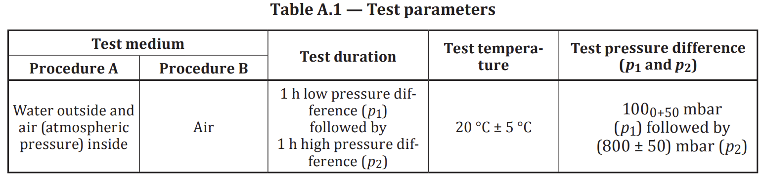
The test parameters in Table A.1 shall be used, if applicable.
The free length, l0, of each pipe shall be at least three times the nominal outside diameter, dn, with a
minimum of 250 mm.
In case of using procedure A, pipes with dn greater than 315 mm and the specified minimum free
length cannot be achieved, a shorter free length can be chosen with a minimum of two times dn, unless
otherwise specified in the referring standard or specification.
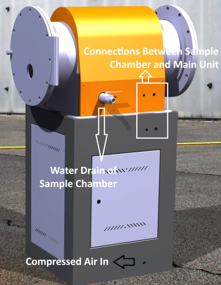
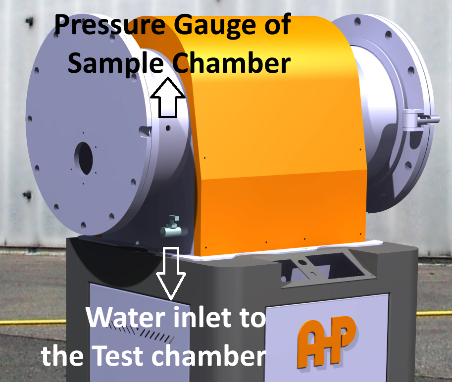
Setup of connections
1- Connect the water and compressed air inlet line. On the sample placement chamber, there are a water inlet, an air outlet, a water drain, connection to the pressure gauge.
water inlet line is at from right side and it is a 1/2″ valve. Air outlet line is at right side and it is a 1/4″ valve (this valve is used for air outlet when filling the tank with water).
The water drain line is used to empty the tank for the disassembly of the sample piece. It is 1″ valve located at the back side of the tank.
2- Connect the main power. Main power is 220V-50Hz single phase. It should be with a ground connection.
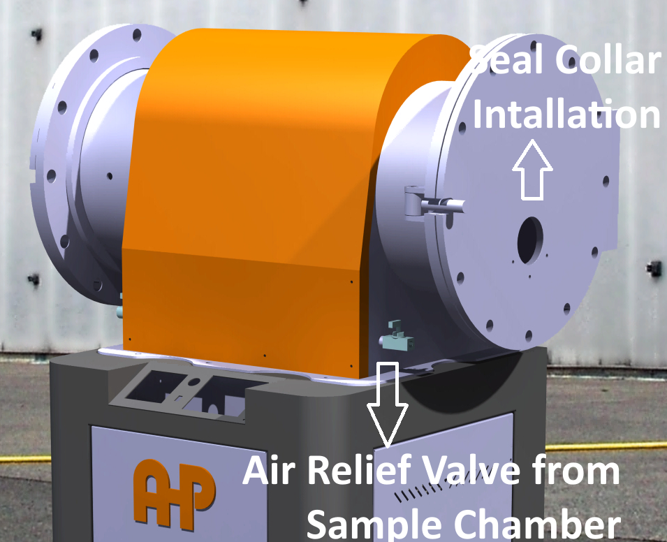
3- Choose the proper size of sealing collar and mount it on both flanges of the water tank(Figure1).
4- Connect the pressure gauge to the 1/4″ connection on the front-left of the water tank.
Using the Touch Panel
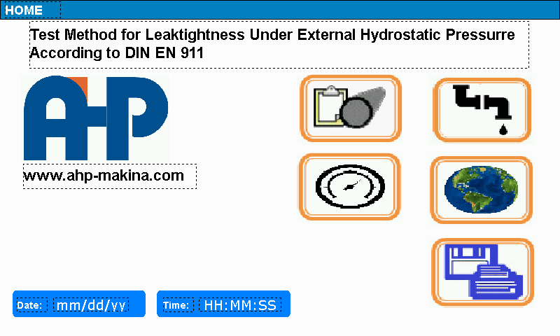
Home screen has access to test page, sample parameter page language setting, saving page and calibration page.


Sample Preparation for Testing
Before going to the touch panel you need to setup sample piece inside the water tank like Figure 1.
First, choose the proper seal collar size for the sample piece and install it on both flanges. Install the sample piece inside the tank and pass both ends of sample piece from seal collar.
Open the drain valve and then open the water inlet to the tank. While filling the tank, note the water level indicator. The water level should pass the sample height.
After filling the tank, you can close the water inlet valve and air outlet valve. Take note of both ends of the sample piece on the seal collars so as not to have any leak from the seals. Now everything is ready to start the test. Steps are as below:
1- Set the sample parameters on the page below.
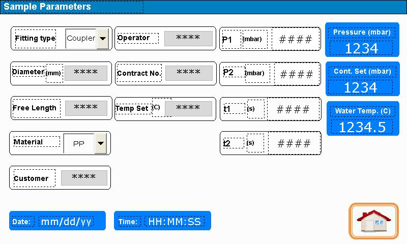
P1 (mbar) : Set the pressure level 1 in unit of mbar
P2 (mbar) : Set the pressure level 2 in unit of mbar
t1 (s) : Time setting of pressure level 1 in unit of seconds
t2 (s) : Time setting of pressure level 2 in unit of seconds
Other parameters on this page are general parameters of sample piece.
2- Go to the Test Page
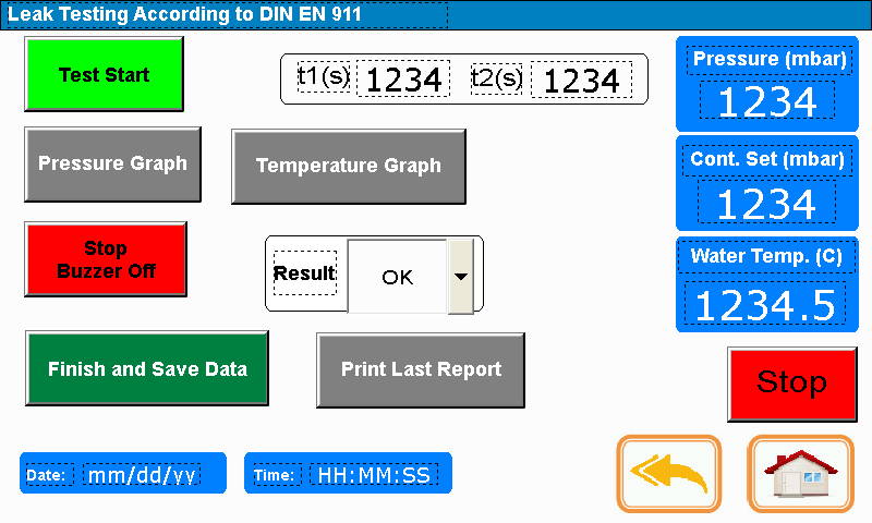
On this page, you can click “Test Start“.
t1(s): indication of time of pressure level 1 in seconds
t2(s): Indication of time of pressure level 2 in seconds
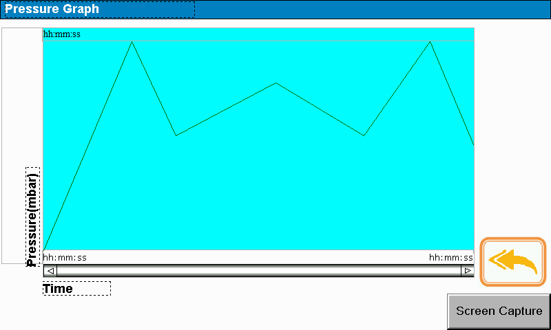
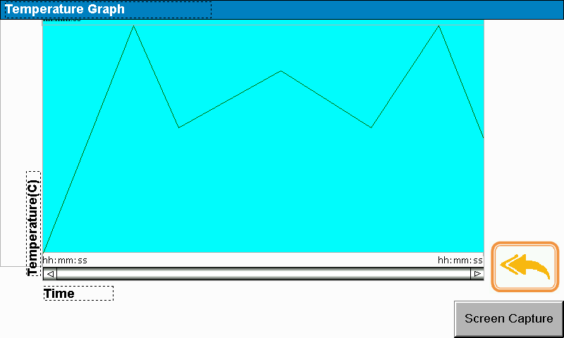
While testing, you can see graphs of pressure and water temperature on these pages. Also, if you connect a flash disk to the machine, you can take a screenshot of the graphs on the flash disk.
Calibration Page for Pressure and Temperature
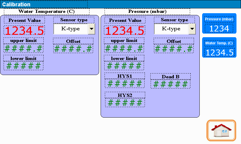
Settings on this page will be done in contact with the admin.
Saving Page
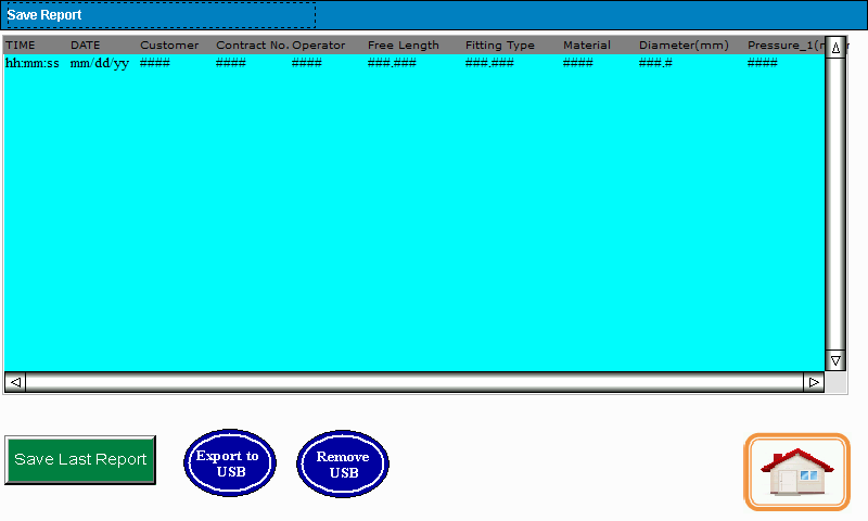
Connect the flash disk to the USB outlet on the front panel. Click on “Save Last Report“. A row of data, including parameters, will be saved on this page. Click on “Export to USB” and an MS EXCEL file will be saved on the flash disk. Then click on “Remove USB”, now you can detach the flash disk from the USB outlet.
Language Page
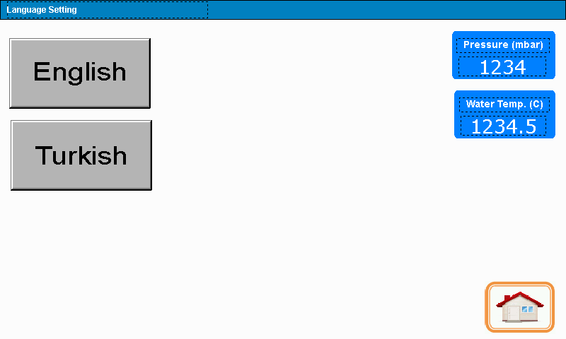
Set the language of touch panel on this page.