4 Requirements
4.1 Approach 1
No fog shall be visible after the test has ended in accordance with 5.1.4.
4.2 Approach 2
No permanent visual condensation shall be permitted in accordance with 5.2.4.
5 Test methods
5.1 Approach 1
5.1.1 Principle
Test specimens are placed in a chamber that is controlled at (50 ± 3) °C. A lamp is positioned in the bottom of the chamber to supply heat and UV radiation. A chilled plate, controlled to a constant temperature of (21 ± 2) °C, is positioned on the centre of each specimen. After 7 days of exposure, the test specimens are examined at arm’s length for fog.
5.1.2 Test specimens
Each test specimen shall measure (355 ± 6) mm by (505 ± 6) mm, and shall be composed of two or three
panes of clear, tinted or coated annealed, heat-strengthened, tempered or laminated glass.
The double-glazed test specimen shall be fabricated with at least one pane of clear, uncoated glass. The
triple-glazed test specimen shall be fabricated with at least one outer pane of clear, uncoated glass. The other outer pane shall be fabricated with a glass that allows easy viewing of fog.
For double-glazed test specimens, the glass and airspace thicknesses shall be 4 mm glass with 12 mm
airspace or 5 mm glass with 6 mm airspace.
For triple-glazed test specimens, 4 mm glass with 6 mm airspaces shall be used.
Tolerance of glass thickness shall be in accordance with ASTM C1036.
Airspace tolerance(s) shall be ± 0,8 mm.
A minimum of two specimens of double-glazed or four specimens of triple-glazed test specimens shall be
submitted for testing.
NOTE 1 However, it is recommended to submit extra specimens in case of breakage.
Triple-glazed test specimens where the intermediate airspace divider is a plastic film shall be acceptable for testing.
NOTE 2 The overall unit thickness of a test specimen has some limits. Testing laboratories are usually able to accommodate 30 mm overall thickness. If testing thicker units, it is necessary to contact the testing laboratory prior to manufacturing to ascertain their capabilities for testing thicker units.
Each specimen shall be permanently and legibly marked with the designation of the manufacturer, the date of fabrication (month or quarter and year) and orientation intended in the field (for test specimens that have been constructed with coated glass).
During all stages of exposure and storage, the test specimens shall be held in a vertical position with equal support to all panes and no compression loading.
The selection of test specimens for testing shall be made at random, except when specimens have been
damaged in transit. Damaged test specimens shall not be tested.
Test specimens representing sealed, insulating glass units that are gas-filled shall be fabricated using the
same hole-sealing and gas-filling techniques as those used during manufacturing. For example, if a gas-filling plug is used in manufacturing, then it should be used in the test specimens. It is not necessary that the specimens be filled with gas provided that the gas is classified as inert.
Test specimens representing products that are normally filled with an inert gas in production may be submitted air filled for this testing as long as they have been manufactured with the same techniques as used in production.
Test specimens representing sealed, insulating glass units that include tubes intended to be left open shall be fabricated with one tube. This tube shall be left open during testing. Test specimens representing sealed, insulating glass units that include tubes intended to be closed off after shipping shall be fabricated with one tube. The exterior end of this tube shall be closed prior to testing.
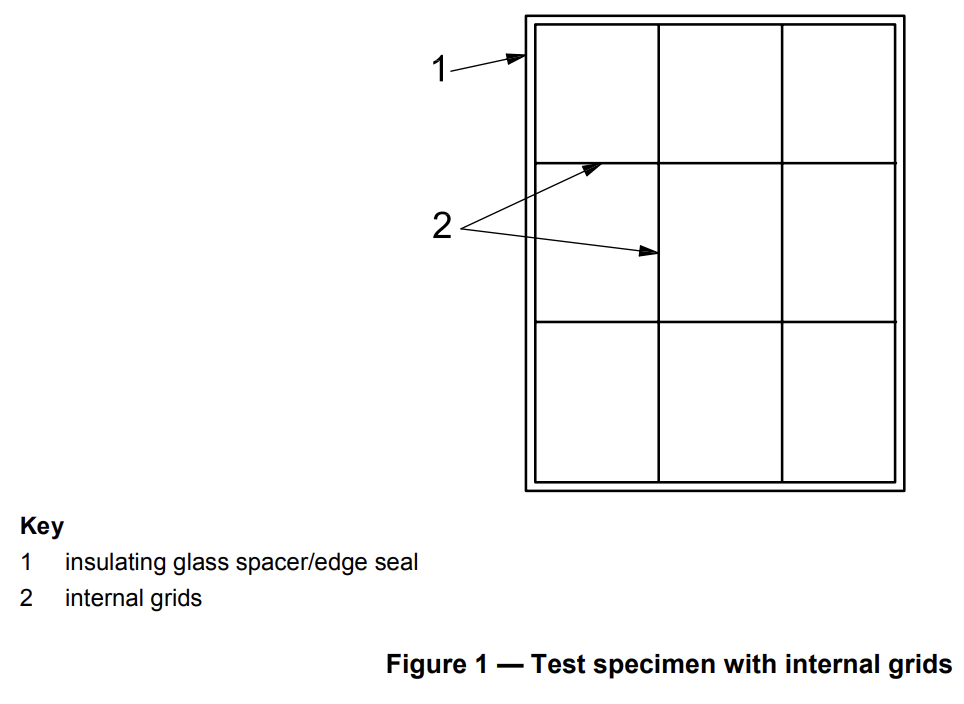
For test specimens representing sealed, insulating glass units that include internal components in the air
space, the grid formed by these components shall divide the test specimen into nine equal areas (3 × 3) (see Figure 1).
The test specimens should be sealed a minimum of 4 weeks from the date of manufacture to allow for
stabilization before testing.
Before testing, the glass surfaces shall be checked to ensure that they are clean.
5.1.3 Apparatus
5.1.3.1 Volatile fog test apparatus
The dimensions and components of the volatile fog test apparatus shall be in accordance with Figure 2. The construction of the apparatus shall be capable of maintaining (50 ± 3) °C. In order to maintain this temperature, a fan shall be mounted in the box. The fan shall run continuously.
The apparatus shall be constructed from sturdy, solid materials that minimize the escape of ultraviolet light into the surrounding area.
Plywood that is at least 12 mm thick has been found to be suitable for this purpose. If plywood is used to
construct the apparatus, the entire interior of the apparatus should be lined with aluminium foil or other
reflective material.
NOTE Stainless steel construction is also acceptable.
The interior of the apparatus shall have a reflective surface.
The test specimen supports shall be located in accordance with Figure 2.
The cooling plates shall be constructed of a conductive material such as copper or brass. The cooling plates shall be nominally 150 mm ± 5 mm in diameter, and shall be placed directly in complete contact with the glass surface for the duration of the test.
Alternatively, a rectangular cooling plate shall have an area of 0,017 7 ± 0,000 6 m2.
The cooling water temperature shall be determined as the water immediately exits the apparatus from each cooling plate as shown in Figure 2. The cooling water temperature at these locations shall be 21 °C ± 2 °C.
The apparatus shall have radiation-shielded thermocouples to continuously monitor the temperature of the apparatus, located in accordance with Figure 2.
5.1.3.2 Ultraviolet light source
WARNING — Light from the ultraviolet sources used in this test method are harmful to the human
body, especially to the eyes. Appropriate protective measures should be observed.
The source shall consist of one ultraviolet lamp. The output of the UV source shall be measured from a
distance of 355 mm ± 5 mm with a long-wave ultraviolet meter and shall not be less than 400 µW/cm2.
5.1.4 Procedure
5.1.4.1 Ensure that the cooling plate is clean and that the contact surface is flat.
5.1.4.2 For double-glazed sealed insulating glass units with low-e coatings, ensure that the cold plate is
located on the low-e coated pane.
5.1.4.3 Mount the two selected test specimens within a volatile fog test apparatus similar to that shown in
Figure 2 and close the lid before turning on the UV lamp.
5.1.4.4 Turn on the UV light source.
5.1.4.5 Maintain all thermocouples (shown in Figure 2 as TC1, TC2, TC3 and TC4) at (50 ± 3) °C. Ensure
that the temperature differential from thermocouple 1 to thermocouple 2 does not exceed 3 °C, and ensure that the temperature differential from thermocouple 3 to thermocouple 4 does not exceed 3 °C.
NOTE The fan and vents can be used to regulate this temperature.
5.1.4.6 Maintain the temperature of the cooling water at (21 ± 2) °C. Determine the temperature of the
cooling water immediately after it leaves the test apparatus for each cooling plate.
Alternatively, an electric chilling apparatus can be used to control the cooling plate at the temperature required in 5.1.4.6. The temperature of the cold plate portion of this device should be determined.
5.1.4.7 Expose the specimens to these conditions for a period of seven days.
5.1.4.8 For triple-glazed, sealed, insulating glass units, ensure that both cavities are tested. Test two
sealed, insulating glass units with the exterior pane (as identified by the manufacturer) towards the cooling plate, and two sealed, insulating glass units with the interior pane (as identified by the manufacturer) towards the cooling plate.
5.1.4.9 After exposure in the test apparatus, remove the test specimens. Examine them carefully for fog
by holding them at arm’s length (approximately 500 mm to 750 mm) from the eyes with light behind the test specimen. Move the test specimen to any angle necessary to thoroughly check the surface of the glass for fogging.
5.1.4.10 If fog is not observed, record the observation and end the test.
5.1.4.11 If fog is observed, record the observation and condition the test specimen(s) for 24 h at 23 ± 3 °C.
After the 24 h period, re-examine the specimen(s) in accordance with 5.1.4.9, then proceed to 5.1.4.12.
5.1.4.12 If fog is not observed after the 24 h observation period, record the observation and end the test.
5.1.4.13 If fog is observed after the 24 h observation period, record the observation and condition the test
specimen at 23 ± 3 °C for an additional six days. After this six day period, re-examine the specimens in
accordance with 5.1.4.9. Record any presence of fog and end the test.
5.2 Approach 2
5.2.1 Principle
The test specimens are conditioned for one week under factory conditions and then placed in the fogging test apparatus. There are three possible choices of apparatus (see 5.2.2), each of which uses a light source to heat and radiate the test specimens with UV. A cold spot is created by chilling or shading the spot. After exposure, the test specimens are visually inspected for evidence of fogging on the interior glass surfaces.
Breakage of glass does not constitute nonconformity; a sealed, insulating glass unit with broken glass may be replaced by a spare test piece and the test repeated.
5.2.2 Apparatus
The following three apparatus may be used for Approach 2:
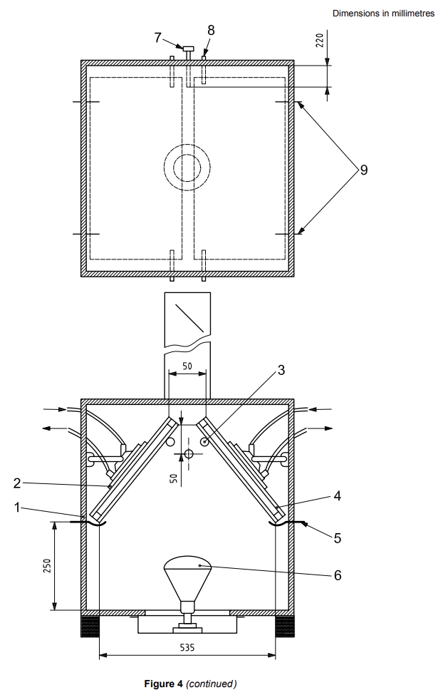
a) British fogging equipment (see Figure 4);
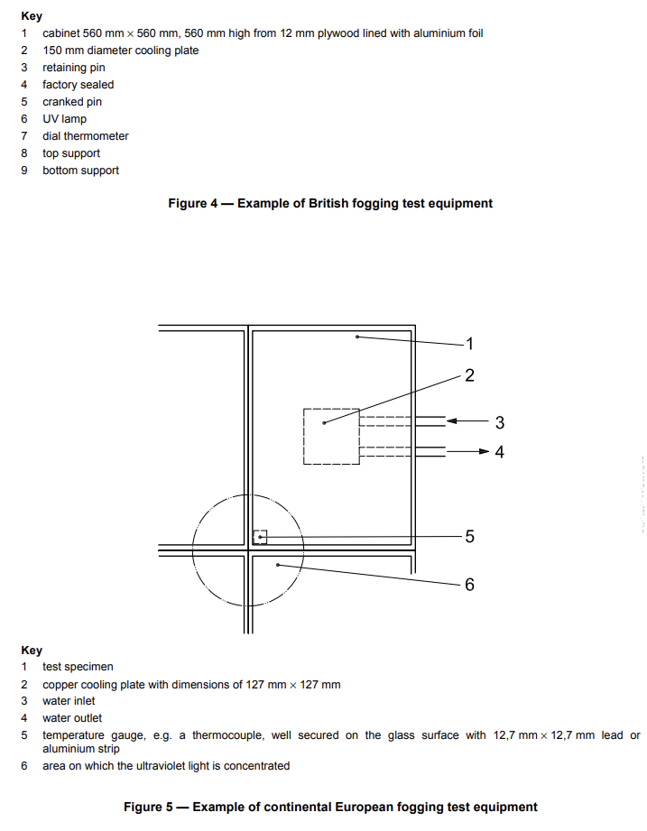
b) continental European equipment (see Figure 5);
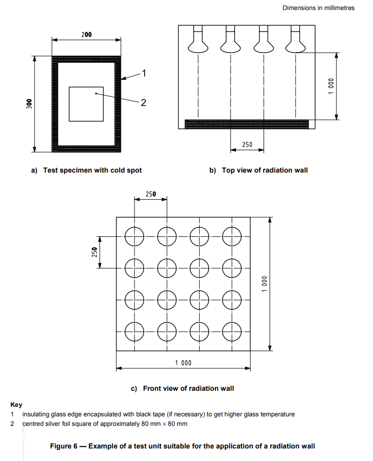
c) radiation wall (see Figure 6).
The British and the continental-European type of equipment requires a method of chilling the cold spot.
Typically, this is done with a water-cooled chilling plate.
The radiation wall uses a silver foil to reflect heat, thus creating the cold spot without the necessity of cooling the glass with water.
5.2.3 Test specimens
A set of sealed insulating glass units consists of two test specimens. The test specimens shall be
representative of the system description (see ISO 20492-1) and shall consist of two panes of 4 mm clear float glass in accordance with EN 572-1 and EN 572-2. The length shall be (502 ± 2) mm and the width
(352 ± 2) mm. The gap shall be 12 mm, or if not manufactured, a gap as near to 12 mm as possible. The
cavity is preferably air filled, but other gases may also be used. Construction details of the edges and corners shall correspond to the edge and corner details in units supplied to the market.
When the system description contains curved insulating glass units with a bending radius equal to or less than 1 m, the test pieces shall be curved as described in EN 1279-1.
5.2.4 Procedure
5.2.4.1 Heat the surface temperature of the test specimens so that at least 20 % to 30 % of the surface
area is between 50 °C to 60 °C.
5.2.4.2 Locate the cold spot in the centre of the test specimen. Ensure that the length and width of the
cold spot is 1/3 of the length and width of the test specimen, or 10 % of the surface area of the test specimen.
5.2.4.3 Ensure that the average cold spot surface temperature is 27 °C to 33 °C lower than the surface
temperature of 20 % to 30 % of the test specimen area noted in 5.2.4.1.
5.2.4.4 Ensure that temperature of the rest of the test specimen is sufficiently high to ensure that all
condensation occurs on the cold spot.
5.2.4.5 Perform the test over a period of (168 ± 4) h.
For heating the relevant component, a lamp, or an arrangement of lamps, may be used, with an ultraviolet
radiation of equal to or more than 40 W/m2 measured in the plane where the units are located. The ultraviolet radiation intensity can be obtained with, for example, a high- pressure mercury lamp with a tungsten filament, simulating sun radiation lamps (300 W at 300 mm from the spot on the surface of the relevant component).
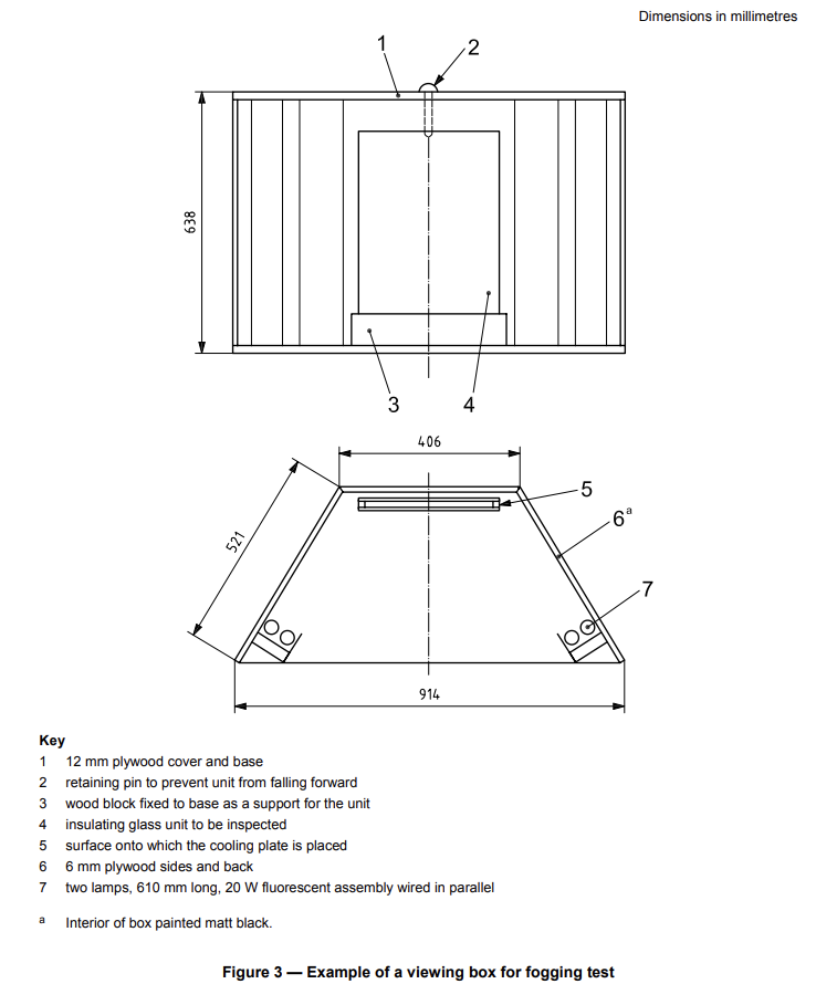
5.2.4.6 Observe the test specimens, by transmission and reflection, for interference and for scattered
light caused by fogging, e.g. clean the test pieces and mount each in turn in a viewing box at eye level.
NOTE: See Figure 3 for an example.
5.2.4.7 Stand directly in front of the test specimen at a distance of approximately 1 m and look for
evidence of dirt or other contamination on the interior of the glass surfaces.
5.2.4.8 If condensation is seen in the viewing box, store the unit between 15 °C and 25 °C for seven days
and re-examine in the viewing box from a distance of 1 m.