5 Apparatus
5.1 General
See ISO 527-1:2012, Clause 5, specifically 5.1.1 to 5.1.4.
5.2 Extensometer
For this part of ISO 527, a gauge length of 75 mm is preferred when a multipurpose test specimen is used.
A gauge length of 50 mm is also acceptable for quality-control purposes or where specified.
If strains are recorded only on one side of the test specimen, ensure that low strains are not falsified by
bending, which may result from even faint misalignment and initial warpage of the test specimen and which generates strain differences between opposite surfaces of the test specimen.
NOTE: Increasing the gauge length leads to higher accuracy, especially for the modulus determination. The absolute accuracy of the measurement of elongation required for a ±1 % accuracy of modulus determination is ±1,5 μm. This is less severe than the ±1 μm needed if a gauge length of 50 mm is used. Furthermore, necking outside of the gauge length will be less frequent.
5.3 Recording of data
See ISO 527-1:2012, 5.1.6.
NOTE For the determination of the tensile modulus under the conditions v = 1mm/min, L0 = 75mm, L = 115 mm and r = 0,0005 mm, the recording frequency for the strain signal greater than or equal to 22 s-1 would be appropriate according to ISO 527-1:2012, Equation 1. This frequency increases as the gauge length increases. With larger gauge length the absolute elongation measured by the extensometer is larger for the same crosshead displacement, i.e the recording instrument will see more data points in the same time span.
6 Test specimens
6.1 Shape and dimensions
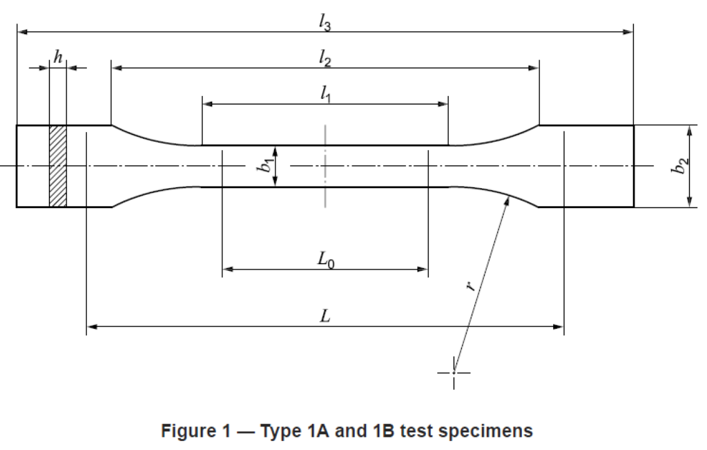
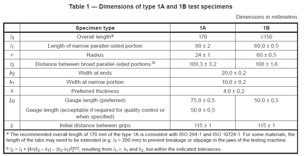
Wherever possible, the test specimens shall be dumb-bell-shaped types 1A and 1B, as shown in Figure 1 and Table 1. Type 1A shall be used for directly injection-moulded multipurpose test specimens, type 1B for machined specimens. Type 1A may also be used for compression-moulded specimens. For the use of proportionally scaled miniaturized specimens, see Annex A and/or ISO 20753.
NOTE 1: At 4 mm thickness, specimen types 1A and 1B are identical to the multipurpose test specimens according to ISO 3167, types A and B, respectively, and to types A1 and A2 of ISO 20753.
For purposes where large numbers of test specimens are to be exposed in limited space, for example, during analysis of environmental influences due to radiation, heat and/or chemicals (see ISO 11403-3), small test specimens of type C of ISO 20753 can be used. In such cases, frequently only the relative change of strength is of interest, and specimens of type CW are particularly useful. To accommodate wall thicknesses of the final application, thicknesses different from those preferred in ISO 20753 may be used.
NOTE 2: Other miniaturized specimens with different scale factors are defined in ISO 20753
6.2 Preparation of test specimens
Test specimens shall be either directly injection- or compression-moulded from the material in accordance with ISO 293, ISO 294-1, ISO 295 or ISO 10724-1, as appropriate, or machined in accordance with ISO 2818 from plates that have been compression- or injection-moulded from the compound, or obtained from cast or extruded plates (sheet). The moulding conditions shall be in accordance with the relevant International Standard for the material or, if none exists, agreed between the interested parties.
Strict control of all conditions of the specimen preparation is essential to ensure that all test specimens in a set are actually in the same state.
All surfaces of the test specimen shall be free from visible flaws, scratches or other imperfections. From
moulded specimens, all flash, if present, shall be removed, taking care not to damage the moulded surface.
Test specimens from finished goods shall be taken from flat areas or zones having minimum curvature.
For reinforced plastics, test specimens should not be machined to reduce their thickness unless absolutely
necessary. Test specimens with machined surfaces will not give results comparable to specimens having nonmachined surfaces.
6.3 Gauge marks
See ISO 527-1:2012, 6.3.
6.4 Checking the test specimens
See ISO 527-1:2012, 6.4.
6.5 Anisotropy
Injection moulded and extruded plates, as well as finished goods, exhibit some degree of anisotropy as a result of flow-induced orientation. The direction dependence of the tensile properties can be assessed by machining specimens parallel and normal to the flow direction characterizing the moulding process. In the absence of information on such directions, specimens shall be machined in directions as agreed between the interested parties.
6.6 Number of test specimens
See ISO 527-1:2012, Clause 7.
7 Conditioning
See ISO 527-1:2012, Clause 8.
8 Procedure
See ISO 527-1:2012, Clause 9.
For measurement of the tensile modulus (see ISO 527-1:2012, 3.9), the speed of testing shall be 1 mm/min for specimen types 1A and 1B (see Figure 1). This corresponds to a strain rate of approximately 1 % min-1. For small specimens see Annex A.
9 Calculation and expression of results
See ISO 527-1:2012, Clause 10.
Annex A
(informative)
Small specimens
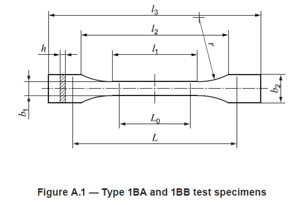
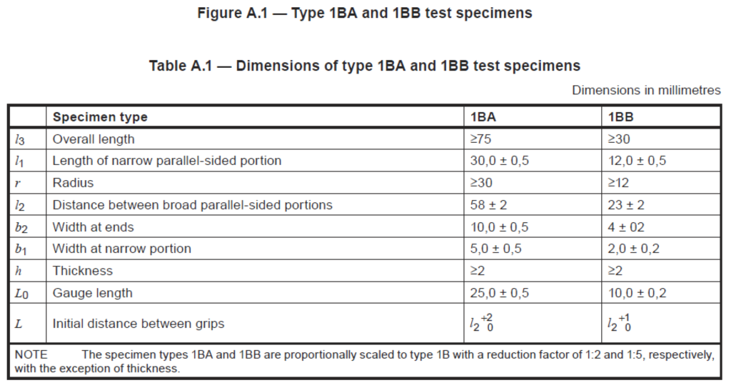
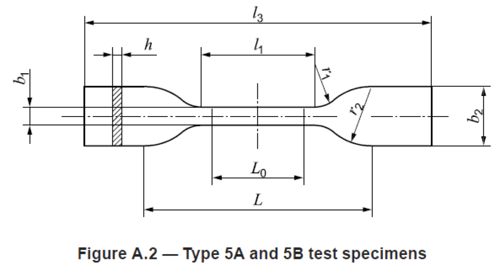
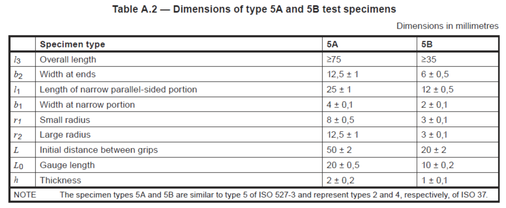
If, for any reason, it is not possible to use a standard type 1 test specimen, specimens of the types 1BA, 1BB (see Figure A.1 and Table A.1), 5A or 5B (see Figure A.2 and Table A.2) or those specified in ISO 20753 may be used, provided that the speed of testing is adjusted to the value given in 5.1.2, Table 1 of ISO 527-1:2012, which gives the nominal strain rate for the small test specimen closest to that used for the standard-sized specimen.
The nominal strain rate is the ratio of the speed of testing (see ISO 527-1:2012, 3.5) versus the initial distance between the grips. Where modulus determinations are required, the test speed is recommended to correspond to a strain rate of 1 % min-1. It may be technically difficult to measure modulus on small specimens because of small gauge lengths and short testing times. Results obtained from small specimens are not comparable with those obtained from type 1 specimens.