
6 Apparatus
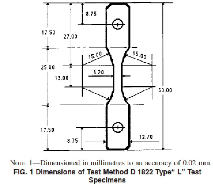
6.1 Blanking Die—A die suitable for cutting test specimens to the dimensions and tolerances shown in Fig. 1.
NOTE 1—The length of the specimen can be changed to suit the design of the test apparatus. However, there should be a constant neck section with length at least 13 mm (0.5 in.) long. The width should be 3.20 mm (0.125 in.).
6.2 Notching Device—A device or machine that can produce a consistent notch depth.
NOTE 2—An evaluation of the notching technique can be performed by quenching a notched specimen in liquid nitrogen and then fracturing it. The notch depth can readily be measured by examining the fracture surface under a reflected light microscope. Other methods of verifying notch depth include viewing the cut specimen on its side in a microscope with the aid of a eyepiece micrometer or a calibrated reticle.
6.3 Blade—A single-edged razor made of carbon steel. The tip profile is that of an arrow rather than that of a chisel point. The sharpness of the point is critical to the cleanliness of the cut which effects the results of the test significantly.
6.4 Stress Cracking Apparatus—Equipment suitable for subjecting test specimens to a tensile stress of up to 13.8 MPa (2000 lb/in.2). The specimens shall be maintained at a constant temperature of 50 ± 1°C (122 ± 2°F) while being totally immersed in a surface-active agent. The solution should be constantly agitated to provide a uniform concentration throughout the bath.
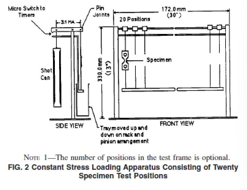
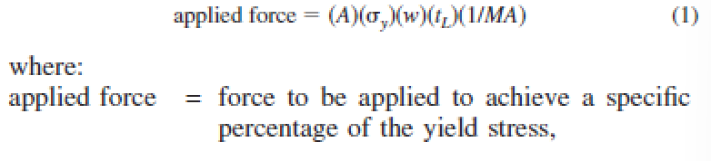
NOTE 3—The apparatus4 shown in Fig. 2 is one type that has been used and is capable of testing up to 20 specimens at a time. This equipment uses a lever system with a mechanical advantage (MA) of three to impose the desired loading on each specimen. The surface-active agent in which the specimens are immersed is contained in an open stainless steel tank. A submersion heater and controller are used to maintain the test temperature. A pump keeps the liquid in a constant state of agitation. A timing clock for each test specimen is also provided to record automatically the failure time of the test specimens to the nearest 0.1 h.
NOTE 4—If “on/off” switches are used to control the timing clock, the switch must be sensitive enough to be turned off under 200 g of the force.
7 Reagent
7.1 The reagent should consist of 10 % surface-active agent with 90 % water. The surface-active agent is Igepal CO-630 that is nonylphenoxy poly(ethyleneoxy)ethanol. The reagent should be stored in a closed container. The reagent in the bath should be replaced every two weeks to maintain a constant concentration.
NOTE 5—In case of dispute, the water should be distilled or deionized at the discretion of the parties involved.
NOTE 6—Other incubation solutions may also be used in the test, provided that the parties involved mutually agree to the changes and state the specific details in the final report.
9 Procedure
9.1 Measure the thickness of each individual test specimen at its minimum cross section to the nearest 0.013 mm (0.001 in.). The variation in thickness should not be greater than ± 0.026 mm (± 0.002 in.) of the nominal thickness of the geomembrane.
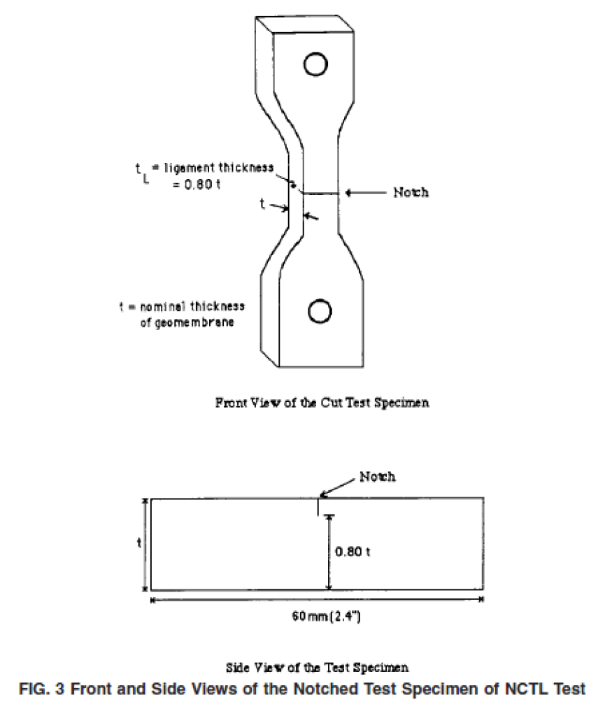
9.2 Cut into each specimen a control imperfection (notch) on one surface as shown in Fig. 3. The depth of the notch should produce a ligament thickness of 80 % of the nominal thickness of the specimen.
NOTE 9—Using this procedure the actual notch depth will vary in accordance with the actual thickness of the test specimen. For example, a sheet of nominal thickness of 2 mm (80 mil) might have thicknesses ranging from 1.98 to 2.08 mm (78 to 82 mil). To obtain a constant hinge thickness of 1.6 mm (64 mil), the notch depth would vary from 0.36 to 0.46 mm (14 to 18 mil), depending upon the actual thickness of the individual test specimens.
9.3 Inspect the edge of the blade for scratches and burrs under normal vision prior to the cut. No single blade shall be used for notching more than 20 test specimens.
9.4 Test specimens are loaded at various percentages of their room temperature yield stress. The applied stress levels should range from approximately 20 to 65 % at maximum increments of 5 %. Three specimens are tested at each stress level to produce statistically significant results.
NOTE 10—To develop the entire curve in a single direction at the recommended values listed above will require ten increments at three specimens each, or 30 individual tests. If both directions are to be challenged, the entire test will require twice as many test specimens.
9.5 For each set of test, the yield stress of the material should be measured according to Test Method D 638 (Type IV). Five specimens should be tested and the average value is used to calculate the applied force. The test specimens should be cut from the same sample and same direction as stated in 8.3.
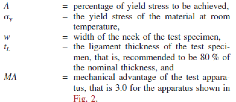
9.6 Calculate the tensile force to be applied to each individual specimen from the equation given below:
9.7 Fill the test bath with reagent, and adjust the temperature to 50 ± 1°C (122 ± 2°F).
NOTE 11—Other temperatures may be used when conducting this test. However, it must be mutually agreed upon by parties involved and the test temperature must be stated in the final report.
9.8 Attach the test specimens to the hooks of the test apparatus.
9.9 Adjust the distance between the lever arm and the switch to a dimension equal to 20 mm (0.80 in.).
9.10 Immerse the test specimens and allow temperature equilibrium to be reached. The minimum time is 30 min. 9.11 Prepare the appropriated weight of lead shot (or other types) required for each individual test specimen according to the calculation in 9.6.
9.12 Load each individual specimen with its respective weight and record the elapsed time to failure to the nearest 0.1 h.
NOTE 12—Other test duration time can be used besides failure time. However, it must be mutually agreed upon by parties involved and the duration of the test must be stated in the final report.
NOTE 13—Expanded polystyrene or other types of insulation can be placed on top of the liquid to minimize the evaporation of water and oxidation of liquid.
NOTE 14—The liquid level in the bath can be maintained by using an automatic water feeder.
9.13 For each of the applied stress levels, calculate the arithmetic mean of the three failure time values and report it as the“ average failure time” for that particular applied stress level.
9.14 Calculate the coefficient of variation as follows and report it to two significant figures:

The value (V) must be less than 15 % for those with average failure time greater than 10 h. If not, three new specimens should be tested at that specific applied stress level again.
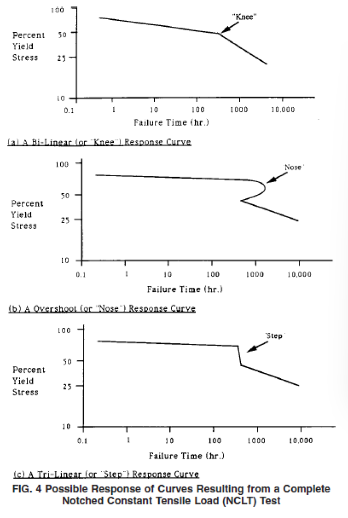
10 Interpretation of Results
10.1 Present the test data in graphic form by plotting the logarithm of percentage yield stress versus the logarithm of the average failure time for each stress level. Three possible types of curves can result, see Fig. 4.
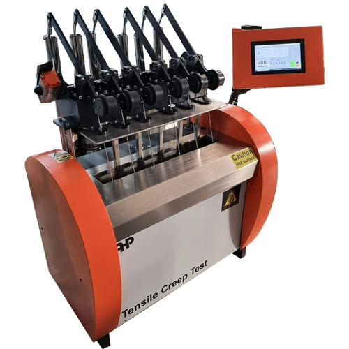
NCTL Tester According to ASTM D 5397 – ECO
- Computerized model
- Windows based software
- software is included
- PLC based
- Circulation system for temperature homogeneity
- Including 6 stations
- One station load cell channel to check forces of each station separately
- Pneumatic based sample elevator
- Lever mechanism force application
- Pneumatic actuator for force application
- Notch making manual press is included
- Press for sample hole clips
- SS304 internal bath
- Stop switch for each channel to record time
- Software according to ASTM D 5397
- Computer is not included (Laptop and installation arm will be quoted separately)
- Easy assembly of samples on testing place
- Force application using dead weight mechanism
- Flange type heating elements
- Blanking die and manual press is included
- Notching device with micrometer
- Microscope for notch depth control is not included (Will be quoted separately in case of customer need)
- Compression-Molding Press (Will be quoted separately in case of customer need)
- Training video is included