
5 Apparatus
5.1 Tensile-testing machine, complying with ISO 527-1 and capable of maintaining a test speed of (20 ± 2) mm/min.
5.1.1 Load cell, which shall comply with Class 1, as defined in ISO 7500-1. The load cell shall be able to accurately measure forces in the range of 40 N for 0,30 mm thick samples and 120 N for 1,0 mm thick samples.
5.1.2 Extensometer, which shall comply with Class 1, as defined in ISO 9513. The traverse displacement shall not be used as a measure of strain. For a 0,30 mm thick specimen, a non-contact extensometer is preferred.
5.1.3 Temperature chamber, to control the temperature at (80 ± 1) °C.
5.1.4 Clamps, remote operation to enable closing and opening without the need to open the temperature chamber is recommended.
5.2 Devices for measuring the thickness and width of the test specimens.
5.2.1 Thickness shall be measured with a device with an accuracy of 0,005 mm and a device with a contact dimension of less than the width of the parallel specimen section (4,0 mm) .
5.2.2 Width shall be measured with a device with an accuracy of 0,01 mm. Care shall be taken not to change the width of the test specimen by deformation. Therefore, it is recommended to use a microscope to measure width to avoid deforming the test specimen.
5.3 Punch knife, in accordance with 6.1 shall be used.
6 Test specimens
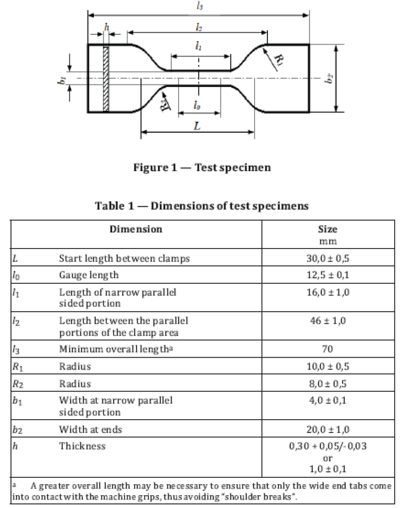
6.1 Test specimen geometry and dimensions
The test specimen geometry as shown in Figure 1 shall be used. A large clamping area of the specimen to avoid slippage in the clamps is required to accurately measure the strain hardening regime.
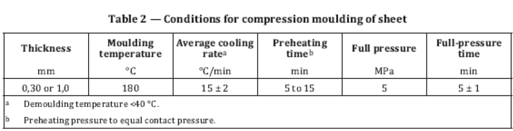
6.2 Test specimen preparation
The PE granules shall be compression moulded into sheets of 0,30 mm or 1,0 mm thickness according
to the moulding conditions given in Table 2, but in case of dispute, the 0,30 mm thickness shall be used.
After compression moulding, annealing of the sheets shall be carried out by conditioning the sheet
for 1 h in an oven at a temperature of (120 ± 2) °C and slowly cooled down to room temperature by switching off the closed temperature chamber with an average cooling rate of less than 2 °C/min. During this operation, free movement of the sheets shall be allowed.
NOTE As cooling will take a long time, it is advised to anneal the samples at the end of the day and allow
cooling of the samples overnight in the temperature chamber.
Five test pieces shall be punched from the pressed sheets using a die for the specimen geometry specified (see 6.1) . The punching procedure shall be carried out in such a way that no deformation, crazes, or other irregularities are present on the test pieces.
The thickness of the samples shall be measured at three points of the parallel area of the specimen. The
lowest measured value for thickness of these measurements shall be used for data analysis (see Clause 8).
Apply the gauge marks on each test specimen equidistant from the midpoint keeping the gauge length, l0.
7 Test procedure
— Measure the exact dimensions of width (b) with an accuracy of 0,01 mm and of thickness (h) with an
accuracy of 0,005 mm of each individual test specimen.
— Condition the test specimens for at least 30 min in the temperature chamber at a temperature of
(80 ± 1) °C prior to starting the test.
— Clamp the test piece in the upper clamp. The clamps shall be chosen to avoid damage and slippage of
the test piece.
— Close the temperature chamber.
— After reaching the temperature of (80 ± 1) °C, clamp the test piece with the lower clamp
— The sample shall remain between the clamps for at least 1 min before the load is applied and
measurement starts.
— Apply a pre-stress of 0,4 MPa with a speed of 5 mm/min.
— During the test, measure the load and elongation sustained by the specimen.
— Extend the test specimen at a constant traverse speed of 20 mm/min Data points shall be collected
from λ = 8,0 until λ = 12,0 or breakage for analysis of the data. If the sample breaks before λ = 8,5,
the sample shall be rejected.
At least five specimens shall be tested. If slippage of the test bar takes place in the clamps, the test result shall be discarded and the test repeated.
8 Data analysis
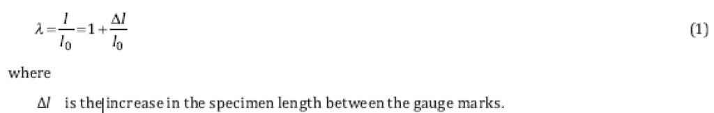
The draw ratio, λ, is calculated from the length, l, and the gauge length, l0, as shown by Formula (1) .
The true stress, σtrue, is calculated according to Formula (2) which is derived on the assumption of
conservation of volume between the gauge marks.
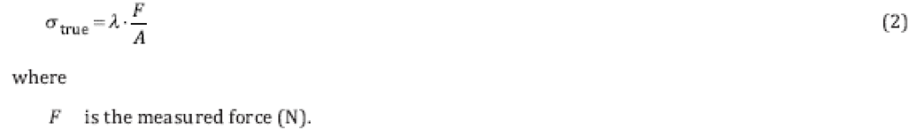
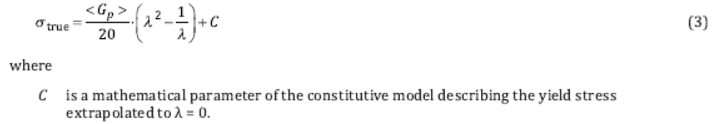
It is important that the initial cross section, A, shall be determined for each individual test bar. The Neo-Hookean constitutive model is represented by Formula (3) and is used to fit and extrapolate the data from which <Gp> (MPa) for 8 < λ < 12 is calculated (see Annex A) .
Accuracy of fit of data (R2) greater than 0,9 shall be achieved.