

A.1 General
This Annex specifies the test method to verify the leaktightness of the seats and packing of a valve/valve bodies made from PE.
A.2 Test piece
The test piece shall be a complete valve with the open ends closed off by, for example, covers, plugs,
flexible seals or end connectors.
The setting time of moulded or fusion-jointed components, as specified by the manufacturer, shall be
completed before commencing conditioning.
A.3 Procedure
A.3.1 Conditioning
Condition the test piece in accordance with this document, see 7.2.
[7.2 Measurement of dimensions
The dimensions shall be measured in accordance with EN ISO 3126 and rounded to the next 0,1 mm. In case of dispute, the measurement shall not be made less than 24 h after manufacture, and after being conditioned for at least 4 h at (23 ± 2) °C.]
A.3.2 Internal leaktightness test (fully closed valve)
Conduct the following procedure; in case of bi-directional valves, both sides of the valves shall be tested:
a) Connect one end of the test piece to the pressure line and the other end to a device capable of detecting leakage;
b) Fill the test piece with the specified test fluid at the specified temperature;
c) Close the valve obturator;
d) Raise the pressure progressively and smoothly in such a way that the test pressure specified in Table 1 is attained within 30 s;
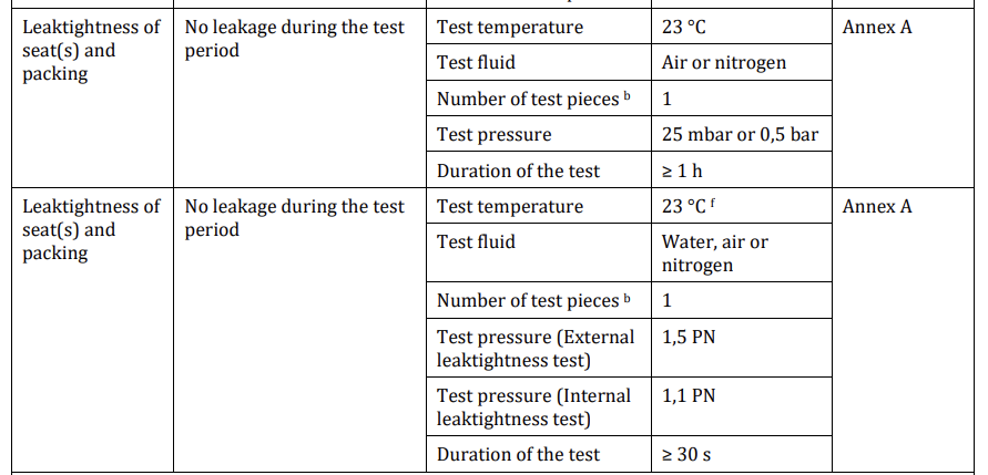
e) Maintain the pressure and temperature for the length of time specified in this document;
f) Observe and record any signs of leakage;
g) Depressurize the test piece.
Valves with independent double seating (such as two-piece obturator or double-seated valves) can be tested by applying pressure between the seats, and each side of the closed valve checked for leakage.
A.3.3 External leak-tightness test (half open valve)
Conduct the following procedure:
a) Put the valve in half-open position;
b) Connect one end of the test piece to the pressure supply and close the other end;
c) Fill the test piece with the specified test fluid at the specified temperature;
d) Raise the pressure progressively and smoothly in such a way that the test pressure specified in
Table 1, is attained within 30 s;
e) Maintain the pressure and temperature for the length of time specified in this document;
f) Observe and record any signs of external leakage;
g) Depressurize the test piece.
A.4 Test report
The test report shall include the following information:
a) full identification of the valve under test;
b) reference to this method of test;
c) test pressure(s), applied to the test piece;
d) test fluid;
e) test duration;
f) results of internal and external leak-tightness testing;
g) any conditions or incidents not detailed by this test method and which might have affected the results;
h) Date of test.
Leak tightness Tester of Seats and Packing for Valves According to EN12201-4 Annex A
- Including both functions of air pressure and water pressure testing
- Air pressure up to 1 bar (other ranges as per customer request)
- Water pressure 10-50 bar (other ranges as per customer request)
- Including water tank of inside dimensions 60*60*60 cm
- Water tank is SS304
- Water temperature control is an option on customer request (Heating and cooling)
- Pressure increase rate control for both water and air pressure control (as per standard, it is important to raise the pressure in 30s)
- PLC controlled
- Includes computer and software for monitoring and controlling
- Graphing and saving of data, both for pressure and temperature
- Software is Windows-Based
- Online remote software support 7/24
- Air inlet pressure 6 bar
- Automatic water level control in case of the heating/cooling option for water temperature control
- A training video is included