
5 Apparatus
5.1 Extrusion plastometer
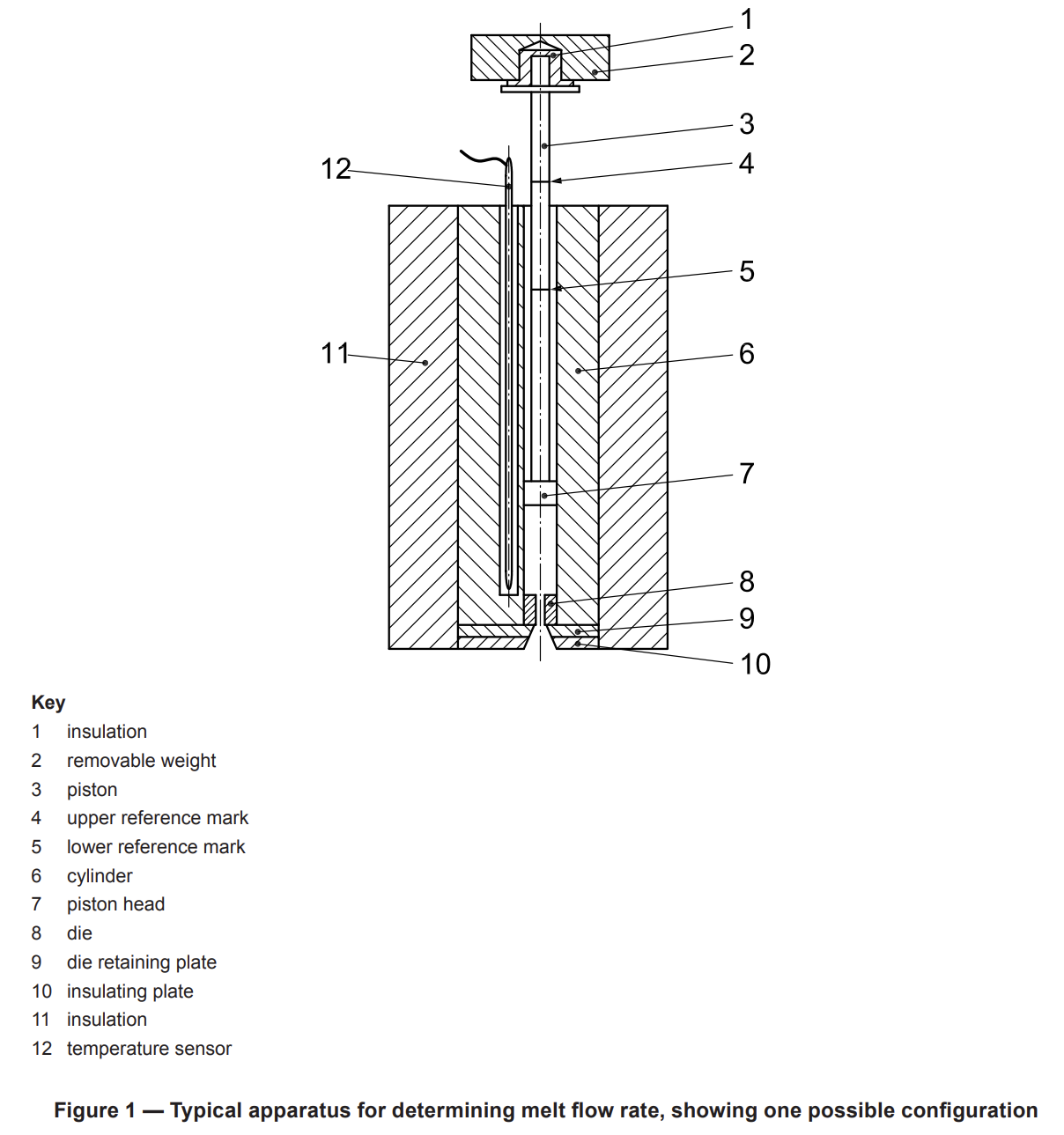
5.1.1 General. The basic apparatus comprises an extrusion plastometer operating at a fixed temperature.
The general design is as shown in Figure 1. The thermoplastic material, which is contained in a vertical cylinder, is extruded through a die by a piston loaded with a known weight. The apparatus consists of the following essential parts.
5.1.2 Cylinder. The cylinder shall have a length between 115 mm and 180 mm and an internal diameter of
(9,550 ± 0,007) mm and shall be fixed in a vertical position (see 5.1.6).
The cylinder shall be manufactured from a material resistant to wear and corrosion up to the maximum
temperature of the heating system. The bore shall be manufactured using techniques and materials that produce a Vickers hardness of no less than 500 (HV 5 to HV 100) (see ISO 6507-1) and shall be manufactured by a technique that produces a surface roughness of less than Ra (arithmetical mean deviation) equal to 0,25 µm (see ISO 4287). The finish, properties and dimensions of its surface shall not be affected by the material being tested.
NOTE 1 For particular materials, it is possible that measurements will be required at temperatures up to 450 °C.
The base of the cylinder shall be thermally insulated in such a way that the area of exposed metal is less than 4 cm2, and it is recommended that an insulating material such as Al2O3, ceramic fibre or another suitable material be used in order to avoid sticking of the extrudate.
A piston guide or other suitable means of minimizing friction due to misalignment of the piston shall be provided.
NOTE 2 Excessive wear of the piston head, piston and cylinder and erratic results can be indications of misalignment of the piston. Regular visual checking for wear and change to the surface appearance of the piston head, piston and cylinder is recommended.
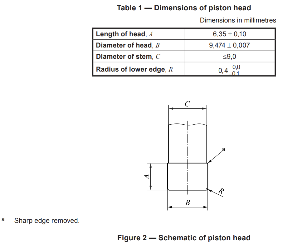
5.1.3 Piston. The piston shall have a working length at least as long as the cylinder. The piston shall have a
head (6,35 ± 0,10) mm in length. The diameter of the head shall be (9,474 ± 0,007) mm. The lower edge of the piston head shall have a radius of (0.4 -0.1) mm and the upper edge shall have its sharp edge removed. Above the head, the piston shall be relieved to <=9,0 mm diameter (see Figure 2).
The piston shall be manufactured from a material resistant to wear and corrosion up to the maximum temperature of the heating system, and its properties and dimensions shall not be affected by the material being tested.
To ensure satisfactory operation of the apparatus, the cylinder and the piston head shall be made of materials of different hardness. It is convenient for ease of maintenance and renewal to make the cylinder of the harder material.
Along the piston stem, two thin annular reference marks shall be scribed (30 ± 0,2) mm apart and so positioned that the upper mark is aligned with the top of the cylinder when the distance between the lower edge of the piston head and the top of the standard die is 20 mm. These annular marks on the piston are used as reference points during the measurements (see 8.4 and 9.5).
A stud may be added at the top of the piston to position and support the removable weights, but the piston shall be thermally insulated from the weights.
The piston may be either hollow or solid. In tests with very low loads the piston may need to be hollow,
otherwise it may not be possible to obtain the lowest prescribed load.
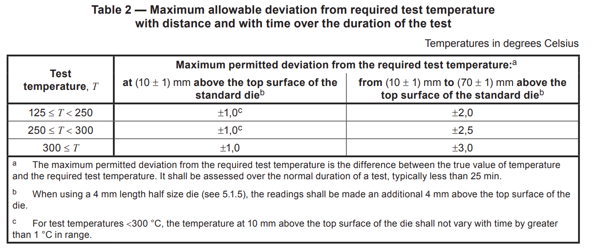
5.1.4 Temperature-control system. For all cylinder temperatures that can be set, the temperature control
shall be such that between (10 ± 1) mm and (70 ± 1) mm above the top of the standard die, the temperature differences measured do not exceed those given in Table 2 throughout the duration of the test.
NOTE The temperature can be measured and controlled with, for example, thermocouples or platinum-resistance sensors embedded in the wall of the cylinder. If the apparatus is equipped in this way, it is possible that the temperature is not exactly the same as that in the melt, but the temperature-control system can be calibrated (see 7.1) to read the in-melt temperature.
The temperature-control system shall allow the test temperature to be set in steps of 0,1 °C or less.
5.1.5 Die. The die shall be made of tungsten carbide or hardened steel. For testing potentially corrosive
materials, dies made of cobalt-chromium-tungsten alloy, chromalloy, synthetic sapphire or other suitable
materials may be used.
The die shall be (8,000 ± 0,025) mm in length. The interior of the bore shall be manufactured circular, straight and uniform in diameter such that in all positions it is within ±0,005 mm of a true cylinder of diameter 2,095 mm.
The bore shall be hardened by a technique that produces a Vickers hardness of no less than 500 (HV 5 to
HV 100) (see ISO 6507-1) and shall be manufactured by a technique that produces a surface roughness of less than Ra (arithmetical mean deviation) 0,25 µm (see ISO 4287).
The bore diameter shall be checked regularly with a go/no-go gauge. If outside the tolerance limits, the die shall be discarded. If the no-go gauge enters the bore to any extent the die shall be discarded.
The die shall have ends that are flat, perpendicular to the axis of the bore and free from visible machining
marks. The flat surfaces of the die shall be checked to ensure that the area around the bore is not chipped. Any chipping causes errors and chipped dies shall be discarded.
The die shall have an outside diameter such that it moves freely within the cylinder, but that there is no flow of material along its outside, i.e. between the die and the cylinder, during the test.
The die shall not project beyond the base of the cylinder (see Figure 1) and shall be mounted so that its bore is co-axial with the cylinder bore.
If testing materials with an MFR >75 g/10 min or an MVR >75 cm3/10 min, a half size die of length
(4,000 ± 0,025) mm and bore diameter (1,050 ± 0,005) mm may be used. No spacer shall be used in the
cylinder below this die to increase the apparent length to 8,000 mm.
The die of nominal length 8,000 mm and bore of nominal internal diameter 2,095 mm is taken to be the
standard die for use in testing. When reporting MFR and MVR values obtained using a half size die, it shall be stated that a half size die was used.
5.1.6 Means of setting and maintaining the cylinder vertical. A two-directional bubble level, set normal to
the cylinder axis, and adjustable supports for the apparatus are suitable for the purpose.
NOTE This is to avoid excessive friction caused by the piston leaning to one side or bending under heavy loads. A dummy piston with a spirit level on its upper end is also a suitable means of checking conformity with this requirement.
5.1.7 Load. A set of removable weights, selected so that the combined mass of the weights and the piston
gives the required load to within a maximum permissible error of ±0,5 %, are mounted on top of the piston.
Alternatively, a mechanical loading device combined with a load cell or a pneumatic loading device with a
pressure sensor, providing the same level of accuracy as the removable weights, may be used.
5.2 Accessory equipment
5.2.1 General
5.2.1.1 Packing rod, made of non-abrasive material, for introducing test samples into the cylinder.
5.2.1.2 Cleaning equipment (see 7.2).
5.2.1.3 Go/no-go gauge, one end having a pin with a diameter equal to that of the die bore minus the allowed tolerance (go gauge) and the opposite end having a pin with a diameter equal to that of the die bore plus the allowed tolerance (no-go gauge). The pin gauge shall be sufficiently long to check the full length of the die using the go gauge.
5.2.1.4 Temperature-calibration device (thermocouple, platinum-resistance thermometer or other
temperature-measuring device) for calibration of the cylinder temperature-indicating device.
A light-gauge probe-type temperature-measuring device that has a short sensing length and which is calibrated at the temperatures and immersion lengths that are to be used when calibrating the cylinder temperature may be used. The length of the temperature calibration device shall be sufficient to measure the temperature at (10 ± 1) mm from the top of the die. The temperature calibration device shall have sufficient accuracy and precision to enable verification of the MVR/MFR instrument to within the maximum permissible errors in temperature as specified in Table 2. When used, the thermocouple should be encased in a metallic sheath having a diameter of approximately 1,6 mm with its hot junction grounded to the end of the sheath.
An alternative technique for verification is to use a sheathed thermocouple or platinum-resistance temperature sensor inserted into a bronze tip with a diameter of (9,4 ± 0,1) mm for insertion in the bore without material present. The tip shall be designed so that it holds the sensing point of the thermocouple or platinum-resistance temperature sensor (10 ± 1) mm from the top surface of the standard die when it rests directly on top of the die.
A further alternative is to use a rod fitted with thermocouples that would allow it to be used to make simultaneous temperature determinations at (70 ± 1) mm, (50 ± 1) mm, (30 ± 1) mm and (10 ± 1) mm above the top of the standard die. The rod shall be (9,4 ± 0,1) mm in diameter so that it fits tightly in the bore.
5.2.1.5 Die plug: A device shaped at one end so that it effectively blocks the die exit and prevents drool of
molten material while allowing rapid removal prior to initiation of the test.
5.2.1.6 Piston/weight support, of sufficient length to hold the piston, and weights as necessary, so that the
lower reference mark is 25 mm above the top of the cylinder.
5.2.1.7 Preforming device. A device for preforming samples, e.g. powders, flakes, film strips or fragments,
into a compacted charge, thereby allowing quick introduction of the charge into the cylinder and to ensure voidfree filling of the cylinder (see Annex C).
NOTE It is possible that there are other options to achieve void-free filling of the cylinder.
5.2.2 Equipment for procedure A (see Clause 8)
5.2.2.1 Cutting tool, for cutting the extruded sample.
NOTE A sharp-edge spatula or a rotating cutter blade with either manual operation or motor drive has been found to be suitable.
5.2.2.2 Timer, with sufficient accuracy to enable cutting of the extruded samples with a maximum permissible error of ±1 % of the cut-off time interval used. For verification, compare the cut-off time intervals with a calibrated timing device over different time intervals of up to 240 s.
NOTE MFRs <5 g/10 min can be measured with the maximum allowed cutting time interval of 240 s. In this case, the maximum permissible error for the cutting time is ±2,4 s. Shorter intervals are allowed, but lead to smaller maximum permissible errors. MFRs >10 g/10 min require cutting times in the order of a few seconds or less. For 1 s, the required maximum permissible error of the cutting time is ±0,01 s or better. Automatic cutters are recommended for MFR values greater than 10 g/10 min.
Where the timing device makes physical contact with the piston or weight, the load shall not be altered by more than ±0,5 % of the nominal load.
5.2.2.3 Balance, with a maximum permissible error of ±1 mg or better.
5.2.3 Equipment for procedure B (see Clause 9): Piston displacement transducer/timer This equipment measures distance and time for the piston movement, using single or multiple determinations for a single charge (see Table 3).
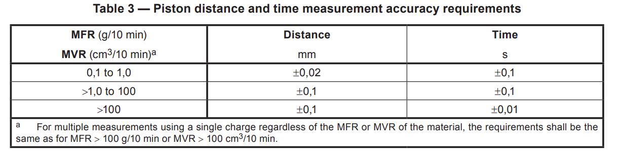
NOTE Compliance with distance accuracy requirements for MFR <= 1 g/10 min and MVR <= 1 cm3/10 min also ensures compliance for MFR > 1 g/10 min and MVR > 1 cm3/10 min.
Where the displacement measurement device makes physical contact with the piston or weight, the load shall not be altered by more than ±0,5 % of the nominal load.
Where the timing device makes physical contact with the piston or weight, the load shall not be altered by more than ±0,5 % of the nominal load.
8 Procedure A: mass-measurement method
8.1 Selection of temperature and load
Refer to the material specification standard for testing conditions. If no material specification standard exists or where MVR or MFR test conditions are not specified therein, use an appropriate set of conditions from Table A.1 based on knowledge of the melting point of the material or processing conditions recommended by the manufacturer.
8.2 Cleaning
Clean the apparatus (see 7.2). Before beginning a series of tests, ensure that the cylinder and piston have been at the selected temperature for not less than 15 min.
8.3 Selection of sample mass and charging the cylinder
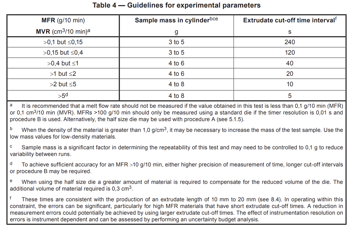
Charge the cylinder with 3 g to 8 g of the sample according to the anticipated MFR or MVR (see Table 4).
During charging, compress the material with the packing rod (5.2.1.1) using hand pressure. Ensure that the charge is as free from air as possible. Complete the charging process in less than 1 minute. The preheat time of 5 min begins immediately after charging of the cylinder has been completed.
NOTE 1 Variations in the packing pressure used to compress the material in the cylinder can cause poor repeatability of results. For the analysis of materials of similar MFR or MVR, the use of the same mass of sample in all tests reduces variability in the data.
NOTE 2 For materials susceptible to oxidative degradation the effect of trapped air on results can be particularly significant.
Immediately put the piston in the cylinder. The piston may be either unloaded or preloaded with the test weight or, for materials with high flow rates, a smaller weight. If the MFR or MVR of the material is high, i.e. more than 10 g/10 min or 10 cm3/10 min, the loss of sample during preheating is appreciable. In this case, use an unloaded piston or one carrying a smaller load during the preheating period. In the case of very high melt flow rates, a weight support should preferably be used and a die plug may be necessary.
During the preheating time, check that the temperature has returned to that selected, within the limits specified in Table 2. To minimize the risk of burns from hot material coming out of the die rapidly, it is recommended that heatresistant gloves be worn during the removal of the die plug.
8.4 Measurements
At the end of the preheat period, i.e. 5 min after completing the charging of the cylinder, in the event that the piston was unloaded or underloaded during the preheat period, apply the required load to the piston. In the event that a die plug was used and the piston was unloaded or underloaded during the preheat period, apply the required load to the piston and allow the material to stabilize for a few seconds before removing the die plug. If a weight support and die plug were both used, remove the weight support first.
NOTE It is possible that for some materials shorter preheating times will be required to prevent degradation. For high melting point, high Tg, low thermal conductivity materials, a longer preheating time can be needed to obtain repeatable results.
Allow the piston to descend under gravity until a bubble-free filament is extruded; this may be achieved before or after loading, depending on the actual viscosity of the material. It is strongly recommended that forced purging of the sample, done either manually or by using extra weights, before commencement of the test be avoided. If any forced purging is required (i.e. to complete the procedure within the specified time limit), it shall be finished at least 2 min before the start of the test. Any forced purging shall be carried out within a period of 1 min. If forced purging is used, it shall be reported in the test report. Cut off the extrudate with the cutting tool (5.2.2.1) and discard. Continue to allow the loaded piston to descend under gravity.
When the lower reference mark on the piston has reached the top edge of the cylinder, start the timer (5.2.2.2) and simultaneously cut off the extrudate with the cutting tool and discard.
Collect successive cut-offs in order to measure the extrusion rate for a given time-interval. Depending on the MFR, choose a time interval so that the length of a single cut-off is not less than 10 mm and preferably between 10 mm and 20 mm (see cut-off time-intervals in Table 4 and its footnote f as a guide).
For low values of MFR (and MVR) and/or materials which exhibit a relatively high degree of die swell, it may not be possible to take a cut-off with a length of 10 mm or more within the maximum permitted cut-off time-interval of 240 s. In such cases, procedure A may be used but only if the mass of each cut-off obtained in 240 s is greater than 0,04 g. If not, procedure B shall be used.
Stop cutting when the upper mark on the piston stem reaches the top edge of the cylinder. Discard all cut-offs containing visible air bubbles. After cooling, weigh individually, to the nearest 1 mg, the remaining cut-offs, preferably three or more, and calculate their average mass. If the difference between the maximum and the minimum values of the individual weighings exceeds 15 % of the average, discard the results and repeat the test on a fresh portion of the sample.
It is recommended that the cut-offs be weighed in order of extrusion. If a continuous change in mass is
observed, this shall be reported as unusual behaviour (see Clause 12).
The time between the end of charging the cylinder and the end of the last measurement shall not exceed
25 min. For some materials, this time may need to be reduced to prevent degradation or cross-linking of the material during the test. In such cases, the use of ISO 1133-2 should be considered.
8.5 Expression of results
8.5.1 General
For testing with the standard die, use 8.5.2. For testing with the half size die, see also 8.5.3.
8.5.2 Expression of results: standard die
The melt mass-flow rate (MFR), expressed in grams per 10 min, is given by the equation
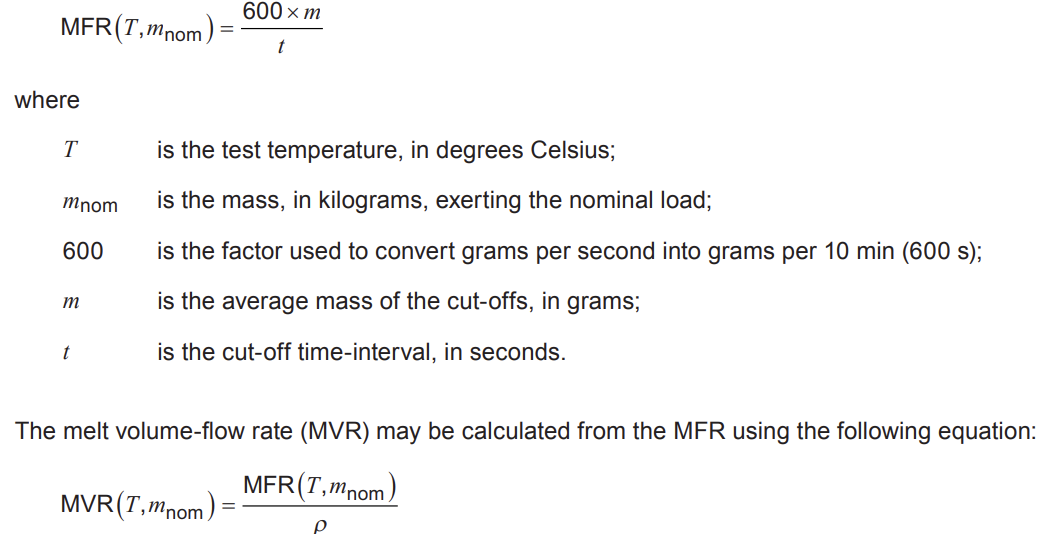
where ρ is the density of the melt, in grams per cubic centimetre, and is given by the material specification standard or, if not specified therein, obtained at the test temperature (9.6.2).
NOTE The density of the melt is required at the test temperature and pressure. In practice, the pressure is low and values obtained at the test temperature and ambient pressure suffice.
For flow properties, MVR is the preferred measure as it is independent of the melt density (Clause 9).
Express the result to three significant figures but with a maximum of two decimal places and record the test temperature and load used, e.g. MFR 10,6 g/10 min (190 °C/2,16 kg), MFR 0,15 g/10 min (190 °C/2,16 kg).
8.5.3 Expression of results: half size die
When reporting results obtained using the half size die the subscript “h” shall be used (see 5.1.5).
The MFR and/or MVR are calculated using the equations in 8.5.2.
Express the result to three significant figures, but with a maximum of two decimal places, and record the test temperature and load used, e.g. MFRh 0,15 g/10 min (190 °C/2,16 kg), MVRh 15,3 cm3/10 min (190 °C/2,16 kg).