
5 Apparatus
5.1 Testing Machine—A testing machine of the constantrate-of-crosshead-movement type and comprising essentially the following:
5.1.1 Fixed Member—A fixed or essentially stationary member carrying one grip.
5.1.2 Movable Member—A movable member carrying a second grip.
5.1.3 Grips—Grips for holding the test specimen between the fixed member and the movable member of the test apparatus can be either a fixed or self-aligning type.
5.1.3.1 Fixed grips are rigidly attached to the fixed and movable members of the test apparatus. Extreme care should be taken when this type of grip is used to ensure that the test specimen is inserted and clamped so that the long axis of the test specimen coincides with the direction of pull through the centerline of the grip assembly.
5.1.3.2 Self-aligning grips are attached to the fixed and movable members of the test apparatus. This type of grip assembly is such that they will move freely into alignment as soon as any load is applied as long as the long axis of the test specimen will coincide with the direction of the applied pull through the centerline of the grip assembly. The specimens should be aligned as perfectly as possible with the direction of pull so that no rotary motion will occur in the grips thereby inducing slippage; there is a limit to the amount of misalignment self-aligning grips will accommodate.
5.1.3.3 The test specimen shall be held in such a way that slippage relative to the grips is prevented as much as possible. Grip surfaces that are deeply scored or serrated with a pattern similar to those of a coarse single-cut file, serrations about 2.4 mm [0.09 in.] apart and about 1.6 mm [0.06 in.] deep, have been found satisfactory for most thermoplastics. Finer serrations have been found to be more satisfactory for harder plastics, such as the thermosetting materials. The serrations should be kept clean and sharp. Breaking in the grips may occur at times, even when deep serrations or abraded specimen surfaces are used; other techniques must be used in these cases. Other techniques that have been found useful, particularly with smooth-faced grips, are abrading that portion of the surface of the specimen that will be in the grips, and interposing thin pieces of abrasive cloth, abrasive paper, plastic, or rubbercoated fabric, commonly called hospital sheeting, between the specimen and the grip surface. No. 80 double-sided abrasive paper has been found effective in many cases. An open-mesh fabric, in which the threads are coated with abrasive, has also been effective. Reducing the cross-sectional area of the specimen may also be effective. The use of special types of grips is sometimes necessary to eliminate slippage and breakage in the grips.
5.1.4 Drive Mechanism—A drive mechanism for imparting to the movable member a uniform, controlled velocity with respect to the stationary member, with this velocity to be regulated as specified in Section 9.
5.1.5 Load Indicator—A suitable load-indicating mechanism capable of showing the total tensile load carried by the test specimen when held by the grips. This mechanism shall be essentially free of inertial lag at the specified rate of testing and shall indicate the load with an accuracy of ±1 % of the indicated value, or better. The accuracy of the testing machine shall be verified in accordance with Practices E4.
NOTE 2—Experience has shown that many testing machines now in use are incapable of maintaining accuracy for as long as the periods between inspection recommended in Practices E4. Hence, it is recommended that each machine be studied individually and verified as often as may be found necessary. It frequently will be necessary to perform this function daily.
5.1.6 Crosshead Extension Indicator—A suitable extensionindicating mechanism capable of showing the amount of change in the separation of the grips, that is, crosshead movement, for the calculation of a strain value for yield and break using the specified gauge length for each. This mechanism shall be essentially free of inertial lag at the specified rate of testing and shall indicate the crosshead movement with an accuracy of ±10 % of the indicated value.
6 Samples and Test Specimens
6.1 A sample can come from sheet, plate, or molded plastics and can be isotropic or anisotropic.
6.2 Record any necessary identification for each sample and maintain that identification with the prepared specimens.
6.3 Test Specimen Dimensions:
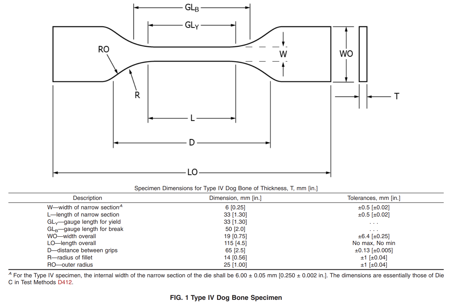
6.3.1 The test specimens shall conform to the dimensions shown in Fig. 1. This specimen geometry was adopted from Test Method D638 and is therefore equivalent to Type IV of said standard.
6.3.2 Test specimens shall be prepared by die cutting from materials in sheet, plate, slab, or similar form.
6.4 All surfaces of the specimen shall be free of visible flaws, scratches, or imperfections. If the specimen exhibits such markings, it should be discarded and replaced. If these flaws or imperfections are present in the new specimen, the die should be inspected for flaws.
NOTE 3—Negative effects from imperfections on the edge of the specimens can severely impact the results of this test and should therefore be carefully monitored. In cases of dispute over the results, inspection of the die and specimen preparation should take place.
9 Speed of Testing
9.1 Speed of testing shall be the relative rate of motion of the grips or test fixtures during the test. The rate of motion of the driven grip or fixture when the test apparatus is running idle may be used, if it can be shown that the resulting speed of testing is within the limits of variation allowed.
9.2 The test speed shall be 50 mm/min [2 in./min] for polyethylene geomembranes and 500 mm/min [20 in./min] for nonreinforced flexible polypropylene geomembranes.
10 Procedure
10.1 Measure the width in accordance with Test Method D374/D374M and thickness of rigid flat specimens (Fig. 1) in accordance with Test Method D5199 for smooth geomembranes and Test Method D5994/D5994M for textured (nonsmooth) geomembranes.
10.2 Place the specimen in the grips of the test apparatus, taking care to align the long axis of the specimen and the grips with an imaginary line joining the points of attachment of the grips to the machine. The distance between the ends of the gripping surfaces, when using flat specimens, shall be as indicated in Fig. 1. Tighten the grips evenly and firmly to the degree necessary to prevent slippage of the specimen during the test, but not to the point where the specimen would be crushed.
10.3 Set the speed of testing at the proper rate in accordance with Section 9, and start the machine.
10.4 Record the load-extension curve of the specimen. 10.5 Record the load and extension at the yield point (if one exists) and the load and extension at the moment of rupture (break point).