
6 Apparatus
6.1 Testing Machine—A testing machine of the constant rate-of crosshead-movement type and comprising essentially the following:
6.1.1 Fixed Member—A fixed or essentially stationary member carrying one grip.
6.1.2 Movable Member—A movable member carrying a second grip.
6.1.3 Grips—Preferably, a set of self-aligning grips for holding the test specimen between the fixed member and the movable member of the testing machine. The grips should minimize both slippage and uneven stress distribution.
6.1.3.1 Fixed grips are rigidly attached to the fixed and movable members of the testing machine. Fixed grips may be used if extreme care is taken to ensure that the test specimen is inserted and clamped so that the long axis of the test specimen coincides with the direction of pull through the center line of the grip assembly.
6.1.3.2 Self-aligning grips are attached to the fixed and movable member of the testing machine in such a manner that they will move freely into alignment as soon as any load is applied so that the long axis of the test specimen will coincide with the direction of the applied pull through the center line of the grip assembly.
NOTE 3—The specimens should be aligned as perfectly as possible with the direction of pull so that no rotary motion that may induce slippage will occur in the grips; there is a limit to the amount of misalignment self-aligning grips will accommodate.
NOTE 4—Grips lined with thin rubber have been used successfully. Grips may be of the self-tightening type. In cases where specimens frequently fail at the edge of the grips, the radius of curvature of the edges of the grips may be increased slightly at the point where they come in contact with the specimen.
6.1.4 Drive Mechanism—A drive mechanism capable of separating the movable member (grip) from the stationary member (grip) at a controlled velocity of 51 mm [2 in.] ± 5 %/min.
6.1.5 Load Indicator—A suitable load-indicating mechanism capable of showing the total tensile load carried by the test specimen held by the grips. The testing machine shall be essentially free from inertial lag at the specified rate of testing and shall indicate the load with an accuracy of ±1 %. The accuracy of the testing machine shall be verified in accordance with Practices E 4.
6.1.6 Crosshead Extension Indicator—A suitable extensionindicating mechanism capable of showing the amount of change in the separation of the grips (crosshead movement).
6.2 Thickness—A micrometer as prescribed in Test Methods D 5947, or an equivalent measuring device, reading to 0.025 mm [0.0001 in.] or less. The pressure exerted by the gage on the specimen being measured shall not distort or deform the specimen. For thin films, # 0.025 mm [0.001 in.], or films which exhibit visual deformation during measurement, a maximum pressure of 70 kPa [10 psi] is recommended. For thicker or stiffer films, the pressure shall be between 160 and 185 kPa [23 and 27 psi].
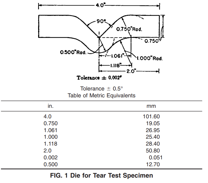
6.3 Die —A die having the dimensions shown in Fig. 1 shall be used to cut all specimens. The 90° angle shall be honed sharp with no radius or have a minimum practical radius. The cutting edge of the die shall have a 5° negative rake, and shall be kept sharp and free from nicks to avoid leaving ragged edges on the specimen. Wetting the surface of the sample and the cutting edges of the die with water may facilitate cutting. The sample shall rest on the smooth, slightly yielding surface that will not damage the die blade. Lightweight cardboard or a piece of leather belting is suitable. Care should be taken that the cut edges of the specimen are perpendicular to its other surfaces and that the edges have a minimum of concavity.
7 Test Specimens
7.1 The test specimens shall be cut out with a die conforming to the dimensions shown in Fig. 1 and shall not vary by more than 0.5 % from these dimensions. The cutting edges of the die shall be kept sharp and free of all nicks to avoid leaving ragged edges on the specimens.
NOTE 5—Caution should be used to ensure all samples are the same dimension if multiple specimens are cut at one time by stacking (layering) film.
7.2 Machine direction specimens are cut perpendicular to the machine direction and transverse direction specimens are cut perpendicular to the transverse direction.
7.3 At least ten specimens shall be tested for each sample, in the case of isotropic materials.
7.4 Test a minimum of ten specimens each in the machine direction and in the transverse direction for each anisotropic test sample.
7.5 Data from specimens which break at some obvious flaw or which break in or at the edges of the grips shall be discarded and additional specimens tested, unless such failures constitute a variable whose effect is being studied.
7.6 Data from specimens which deviate markedly from the mean value of all tests shall be rejected if the deviation of the doubtful value is more than five times the standard deviation from the mean value obtained by excluding the doubtful results.
NOTE 6—For certain materials whose properties vary considerably throughout the film or sheeting, as many as 50 specimens cut from random portions of the sheet must be tested if reliable tear resistance data are desired.
9 Procedure
9.1 An initial jaw separation of 25.4 mm [1 in.] shall be power-activated. The rate of travel of the power activated grip shall be 51-mm [2-in.]/min.
NOTE 7—In this test method, resistance to tear is calculated from the maximum load recorded. In testing most plastics, this maximum load is generated at the onset of tearing across the 13-mm [0.5-in.] testing width of the specimen.
9.2 Measure the thickness of the specimen at several points in the notched area to the accuracy limits of the measuring devices specified in 6.2. Record the average thickness in microns [mil].
9.3 Place the specimen in the grips of the testing machine so that the long axis of the enlarged ends of the specimen is in line with the center line of the grip assembly.
9.4 After complete rupture of the specimen, the maximum tearing load in newtons [pounds-force], and the maximum extension in mm [in.] shall be recorded.
10 Calculation
10.1 Calculate the mean maximum resistance to tearing and the maximum extension for all specimens tested in each principal direction of orientation. Record maximum tear resistance expressed in newtons [pounds-force] to three significant figures and maximum extension expressed in mm [in.] to two significant figures.
NOTE 8—Resistance to tear may be expressed in newtons per micron, [pounds-force per mil] of specimen thickness, where correlation for the particular material being tested has been established. However, it should be realized that a comparison between films of dissimilar thickness may not be valid.
10.2 Calculate standard deviation.