
3 Principle
The scattered and unscattered light energy of a wavelength of 540 nm to 560 nm passing through a test piece cut from a pipe or fitting is measured and expressed as a percentage of the incident light energy on the test piece.
4 Apparatus
4.1 Photoelectric cell, used such that the response of the reading or recording apparatus is a linear
function of the light intensity, from the maximum intensity Im down to at least 0,01 Im. The detector shall be mounted at right angles to the optical axis to ensure that all light passing through the sample is measured. An integrating sphere may be used to facilitate measurements. The incident beam shall be centred on the entrance port and pass along the sphere’s diameter.
If the integrating sphere is used, the internal surface should have a white, diffusely reflecting surface with a reflectance of greater than 70 %. The sphere should include baffles so that neither the incident light flux nor the radiation via the test piece can impinge directly onto the detector.
4.2 Adjustable-power arc or incandescent lamp, the intensity of light of which is constant to ± 1 %. A
filter or other means shall be provided to limit the spectrum of the light to a wavelength of 540 nm to 560 nm, unless the referring standard specifies otherwise.
4.3 Diaphragm and optical lenses, adjusted to obtain a parallel-sided and symmetrical incident beam
whose width is adjusted according to the size of the test piece, ensuring that all light is directed onto it, and small enough to enable all light passing through to be detected by the apparatus used.
A rectangular patch of light shone on the axis of the test piece is preferred. It is recommended that the width of the light beam should not extend across more than 0,25 to 0,3 times the outside diameter of the test piece to prevent light leakage around the side of the test piece. The maximum dimension of the light beam should not be more than 0,5 to 0,7 times the diameter of the instrument entrance port.
4.4 Support, arranged so that it maintains the surface of the test piece to be examined perpendicular to the optical axis.
5 Test pieces
The thinnest wall product in a manufacturer’s range shall be tested. Take a suitable length of the pipe, or the fitting to be tested. Cut into four strips, equally spaced around the circumference.
If it is difficult to meet the recommendation given for the width of the light beam when used for measurement of small diameter pipe, the test piece may be flattened, provided no significant change in thickness occurs (see the second paragraph of 4.3).
6 Procedure
6.1 Setting up the equipment Check
a) the alignment of the installation,
b) that the reading given by the photoelectric cell is zero in the absence of light, ensuring that the photoelectric cell is protected from incident daylight,
c) that the reading is 100 % in the light emitted by the luminous source in the absence of the test piece,
d) that the reading using an opaque sheet of plastic or other material is of an opacity level of less than 2%, calibrated by a reference standard,
e) the accuracy of the reading, using standard calibrated samples or filters that give an absorption
percentage of about 0,2 % — an accuracy of at least 0,05 % in the range of 0 to 0,2 % is considered desirable.
6.2 Measurement
6.2.1 Record the reading of maximum light energy Im received from the light source in the absence of the test piece.
6.2.2 Place the test piece on the support (4.4) and position against the detector or integrating sphere port, ensuring that it is positioned centrally with respect to the light source and perpendicular to it.
The convex (outer) surface of the pipe or fitting test piece shall face the light source.
NOTE In practice, light will fall on the outer surface of the product and therefore the orientation of the test piece has been chosen to represent a pipe or fitting in service.
6.2.3 Record the reading of light energy, I, that has passed through the wall of the test piece.
6.2.4 Make three measurements along the length of each of the four test pieces.
7 Determination of opacity
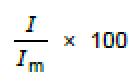
7.1 Calculate the percentage of light transmitted through the test piece using the following equation:
7.2 Take the mean of the three measurements made on each test piece.
7.3 Take the highest of the mean values determined from the four test pieces as the value of opacity.
8 Test report
The test report shall include the following information:
a) a reference to this International Standard and the referring standard;
b) all details necessary for complete identification of the test sample (manufacturer, type of product, polymer used, production date);
c) the value of opacity, i.e. the percentage of incident light energy transmitted through the test piece;
d) any factors which may have affected the results, such as incidents or operating details not specified in
this International Standard;
e) the date of the test.
Annex A
(informative)
Recommended maximum light transmission for opaque pipes and fittings
A.1 Recommended limit
If the referring standard specifies that the pipe and fittings shall be opaque, the maximum acceptable limit for the amount of light which may pass through the wall of the pipe or fitting should be 0,2 % when determined in accordance with this method. This limit is considered sufficient to suppress the growth of algae within such a pipe or fitting.
A.2 Calibration
The calibration between 1 % and 0,1 % can be checked by using a neutral density filter of a density of
between 2,0 and 3,0 (see 6.1). These filters are available from most national calibration laboratories.
Check our YouTube channel for videos of the products, ask any questions on WhatsApp: