4 Apparatus
4.1 Constant-elongation measurements
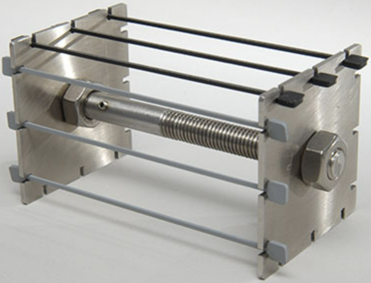
4.1.1 Straining device, consisting of a metal rod or other suitable guide fitted with pairs of holders, one
fixed and one moveable, for the ends of the test piece. The holders shall be in the form of self-tightening
clamps for strip test pieces, in the form of jaws to hold tab (enlarged) ends, and in the form of flat pulleys
of about 5 mm width and 10 mm diameter for ring test pieces.
If so desired, a means of operating the moving holder other than by hand may be provided, for example
a threaded rod. Suitable stops or graduations may also be provided to avoid over-extension in the initial
straining of the test piece.
The straining device shall be so designed that, when used at high temperatures in an oven, it can be
placed with the reference length of the test piece perpendicular to the direction of the air flow. It shall
also be of minimum mass in order to avoid excessive lag in the attainment of temperature equilibrium
after its introduction into the oven.
A multiple-unit straining device may be used, provided that the foregoing requirements are met.
4.1.2 Oven, conforming to the requirements of ISO 188 (if the test is to be carried out at a temperature
above the standard laboratory temperature). For short heating times, controlled air flow is not necessary.
4.1.3 Length-measuring device, capable of measuring the reference length of the test piece to the
nearest 0,1 mm.
For strip test pieces, a marker shall be provided to mark the length used as the reference length.
For ring test pieces, the reference length may be the inner diameter of the ring, in which case a graduated
cone allowing measurements to be made to the nearest 0,1mm shall be used. Alternatively, if measurements are to be made on a straight reference length, a rigid channel, 3,5 mm deep and 20 mm wide for large ring test pieces and 1,75 mm deep and 10 mm wide for small ring test pieces, shall be provided for straightening portions of such test pieces during marking and measuring of the reference length.
4.2 Constant-load measurements
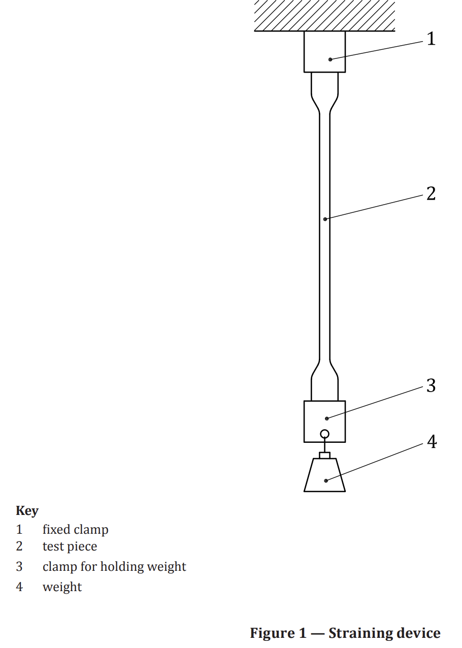
4.2.1 Straining device, comprising clamps and weights, or equivalent, for loading the test pieces
(see Figure 1).
4.2.2 Thickness- and width-measuring device, comprising a gauge for measuring the thickness and,
where appropriate, the width of the test piece in accordance with ISO 23529:2010, method A.
The width of die-cut test pieces shall be taken as the distance between the cutting edges of the die
in the narrow part, in which case a device capable of measuring the width to the nearest 0,05 mm in
accordance with ISO 23529 shall be provided.
4.2.3 Length-measuring device, capable of measuring the reference length to the nearest 0,1 mm.
5 Calibration
The test apparatus shall be calibrated in accordance with the schedule given in Annex A.
6 Test pieces
6.1 Preparation
Test pieces shall be prepared in accordance with ISO 23529. They shall be cut from flat sheet
2 mm ± 0,2 mm thick (except large ring test pieces, which shall be cut from sheet 4 mm ± 0,2 mm thick)
prepared by moulding or slitting and buffing in accordance with ISO 23529.
Strip test pieces and strip test pieces with enlarged ends shall be cut using a sharp die with a cutter as
specified in ISO 23529.
Ring test pieces shall be cut from sheet by means of a pair of concentric circular dies or rotating cutters.
The separation of the two cutting edges shall not differ from the average value by more than 0,05 mm.
6.2 Test pieces for testing under constant elongation
6.2.1 Strip test pieces
Strip test pieces shall be between 2 mm and 10 mm wide. A width of 6 mm is preferred.
The length of any given strip depends on the selected reference length and the type of straining device.
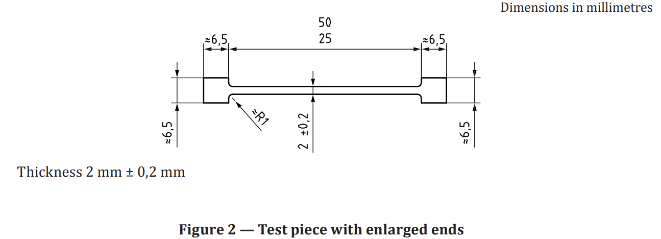
6.2.2 Strip test pieces with enlarged ends
Test pieces with enlarged ends shall be as shown in Figure 2, with a narrow section of length between
25 mm and 50 mm which shall be used as the reference length.
6.2.3 Ring test pieces
Ring test pieces shall be of one of the following sizes:
Large ring test piece:
— thickness: 4 mm ± 0,2 mm;
— outer diameter: 52,6 mm ± 0,2 mm;
— inner diameter: 44,6 mm ± 0,2 mm.
Small ring test piece:
— thickness: 2 mm ± 0,2 mm;
— outer diameter: 33,5 mm ± 0,2 mm;
— inner diameter: 29,5 mm ± 0,2 mm.
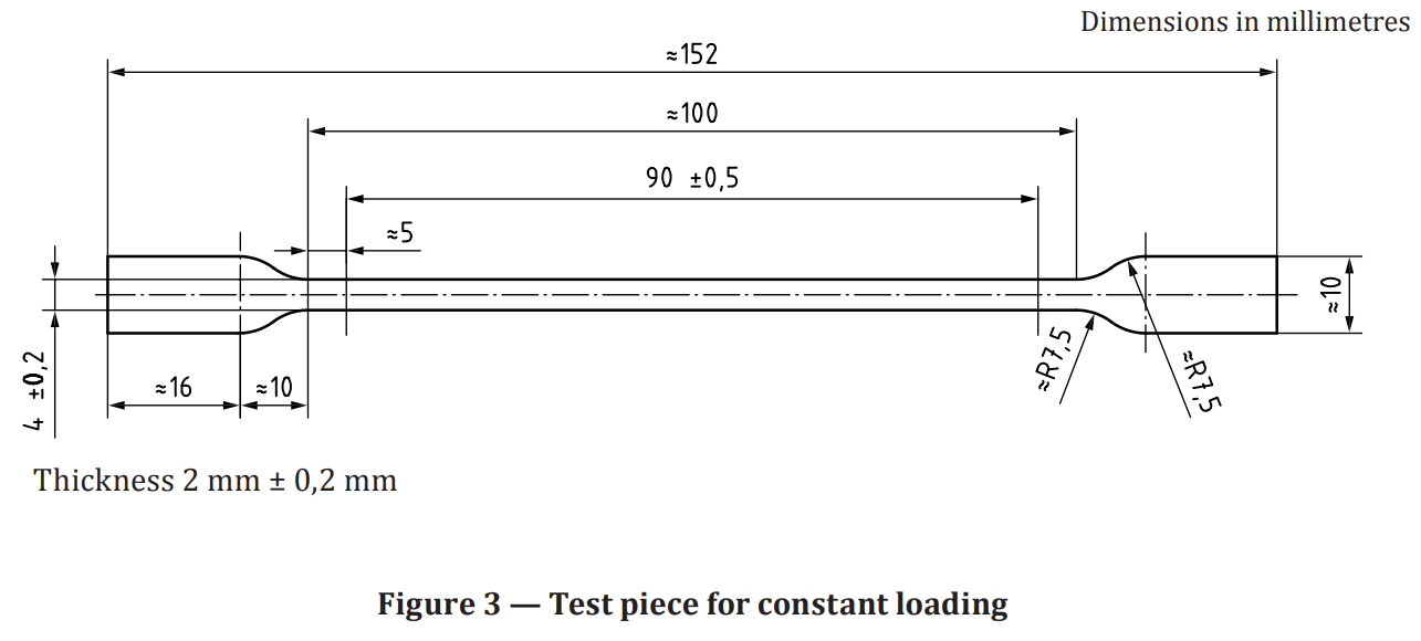
6.3 Test pieces for testing under constant load
Test pieces shall have the shape and dimensions shown in Figure 3.
7 Procedure
7.1 Testing under constant elongation
7.1.1 Measurement of the test pieces
Measure the unstrained reference length (L1) of each test piece to the nearest 0,1 mm at standard
laboratory temperature. Insert the test pieces in the straining device in the appropriate way.
7.1.2 Stretching the test pieces
Extend the test pieces to the required strain. When testing ring test pieces, rotate the pulleys slightly
by hand to equalize the strain in the two halves of the ring. Ensure that the reference length remains
centralized between the two pulleys.
Between 10 min and 20 min after the specified strain has been reached, measure the strained reference
length (L2) to the nearest 0,1 mm. When the inner diameter of ring test pieces is used as the reference
length, it can be calculated from the diameter of the pulleys and the distance between them, measured
to the nearest 0,1 mm. If the strain, calculated as specified in 7.1.4.1, does not conform to the appropriate
standard value, taking into account tolerances, discard the test piece and prepare and test a replacement
test piece with a modified applied strain.
7.1.3 Exposure at the test temperature
7.1.3.1 Tests at standard laboratory temperature
Maintain the strained test pieces at the standard laboratory temperature.
Immediately following the end of the test period, release the strain, remove the test pieces from the
clamps or pulleys and lay them free on a flat non-sticky wooden surface. After 30+3 min, measure the
reference length to the nearest 0,1 mm (L5).
7.1.3.2 Tests at temperatures other than standard laboratory temperature
Between 20 min and 30 min after the specified strain has been reached, place the strained test pieces in
an oven operating at the test temperature and leave them there for the specified period.
There are three methods of cooling the test pieces and releasing the strain, of which method A is preferred.
Method A
At the end of the test period, remove the straining device from the oven, immediately release the strain,
remove the test pieces from the clamps or pulleys and lay them on a flat non-sticky wooden surface.
After 30+3 min, measure the reference length to the nearest 0,1 mm.
Method B
At the end of the test period, remove the straining device from the oven but leave the test pieces in the
strained condition. After 30+3 min, release the strain, remove the test pieces from the clamps or
pulleys and lay them on a flat non-sticky wooden surface. After a further 30+3 min, measure the reference length to the nearest 0,1 mm.
Method C
At the end of the test period, release the strain with the test pieces still in the oven held at the test
temperature. After 30+3 min, remove the straining device from the oven, remove the test pieces from
the clamps or pulleys and lay them on a flat non-sticky wooden surface. After a further 30+3 min, measure the reference length to the nearest 0,1 mm.
7.1.4 Test conditions
7.1.4.1 Strain
Calculate the strain λ, in %, using the equation:
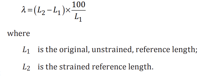
The strain shall be one of the following values:
15 % ± 1,5 %
20 % ± 2 %
25 % ± 2,5 %
50 % ± 5 %
75 % ± 7,5 %
100 % ± 10 %
200 % ± 10 %
300 % ± 10 %
The strain values should be selected in accordance with the type of rubber (vulcanized or thermoplastic)
and with the final application. For vulcanized rubbers, it is recommended that elongations greater than
one third of the elongation at break at the test temperature should not be used. The strain value of 100 %
is the preferred one, unless the above considerations dictate otherwise. For thermoplastic rubbers
which give a yield point, only results calculated at strain values below the yield point are valid. When
possible, the value 20 % ± 2 % is preferred for thermoplastic rubbers.
7.1.4.2 Test period
The test pieces shall normally be strained for a period of 24-2 h, 72-2h or 168-2h, the period commencing 30 min after the strain has been applied. If a longer test period is required, it shall be selected from those given in ISO 23529.
7.1.4.3 Temperature of test
The temperature of test shall be selected from those given in ISO 23529.
If no temperature is specified in the relevant product specification, 70 °C ± 1 °C is recommended.
7.2 Testing under constant load
7.2.1 General
Measure the length of the test piece between the reference marks (L1), the thickness and the width at
standard laboratory temperature.
Clamp the test pieces into the straining device and load them to a stress of 2,5 MPa ± 0,1 MPa, based on
the original cross-sectional area of the test piece. The load shall be applied without shock.
If, during testing, a stress of 2,5 MPa proves to be too large, a stress of 1,0 MPa may be used.
7.2.2 Elongation
30 s ± 2 s after loading the test piece, measure the distance between the reference marks (L2).
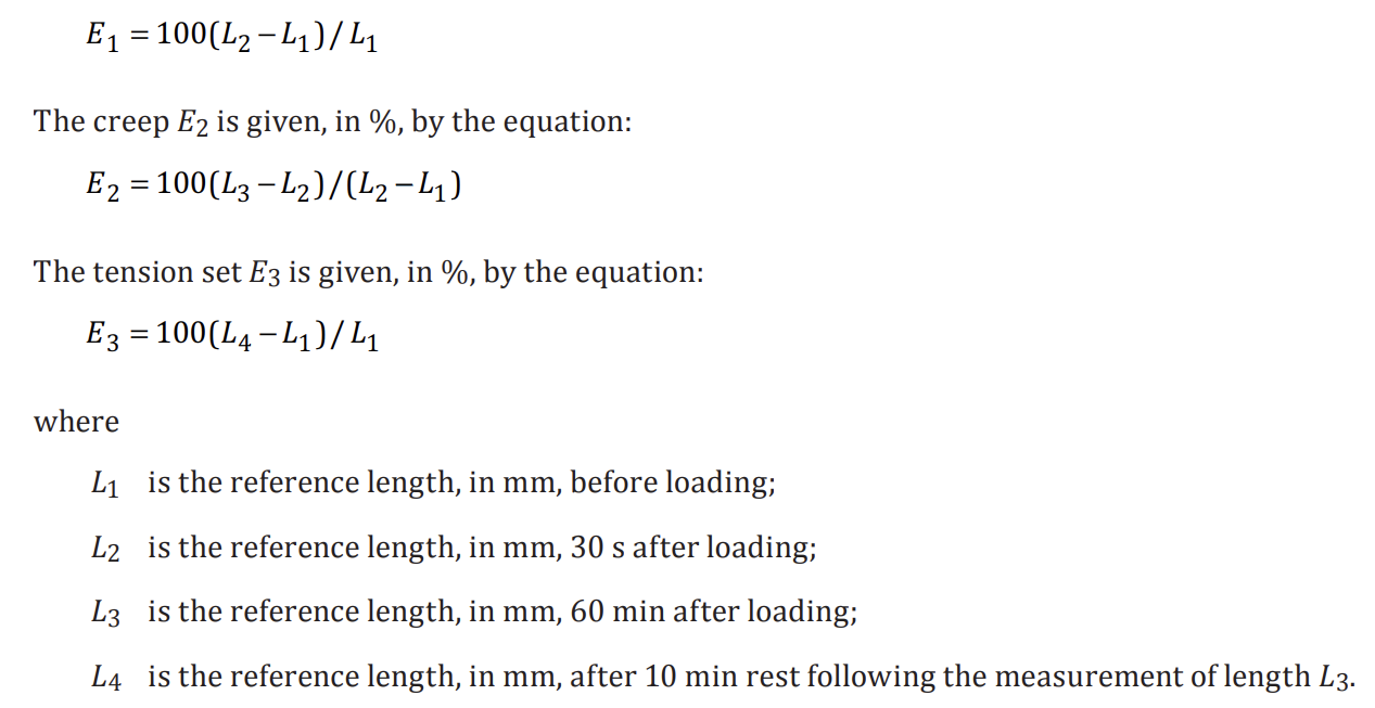
7.2.3 Creep
60 min ± 1 min after loading the test piece, measure the distance between the reference marks (L3).
7.2.4 Tension set
After the creep measurement, unload the test piece, remove it from the straining device and allow it to
rest on a flat non-sticky wooden surface for 10 min ± 1 min. Measure the distance between the reference
marks again (L4)
8 Expression of results
8.1 General
Calculate the individual test results as shown in 8.2 or 8.3. In each case, calculate the mean value of the
results for the three test pieces. The individual values for the three test pieces shall be within 10 % of
the mean value. If they are not, repeat the test using three further test pieces and report the median of
all six results in the test report.
8.2 Constant elongation
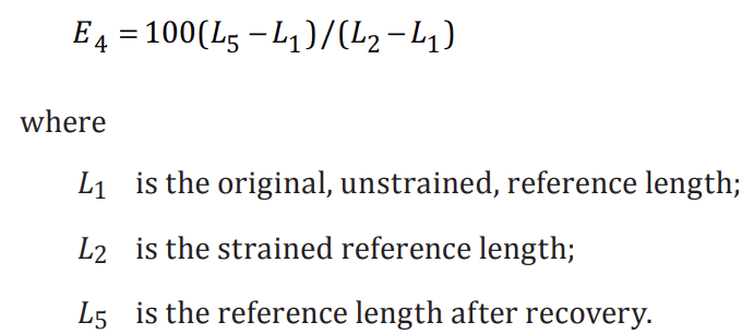
The tension set E4 is given, in %, by the equation:
8.3 Constant load
The elongation E1 is given, in %, by the equation:
Testing Tension Set in Elastomeric Materials
Tension set can be used either with constant strain (here called method A) or constant load (method B), meaning you either keep it at a certain elongation for a set duration or use a certain weight.
Related Standards
ISO 2285
Introduction
Tension set testing with a constant load has been used in Sweden long before international standardized tests of rubber materials became dominating. Tension set can be used either with constant strain (here called method A) or constant load (method B), meaning you either keep it at a certain elongation for a set duration or use a certain weight. The first method is similar to compression set, in that it uses a set elongation and then measure how well the material springs back. This is either done at lab temperature or elevated temperatures. Tension set using constant load is usually performed in lab temperature and gives information about the elongation, creep and tension set at said load after a certain time.
Method A requires a rig that can keep the samples at the set strain but is otherwise very accessible. Method B can probably be considered even more accessible, since all that is required is customizable weights and clamps to hang onto the sample bodies and some way to measure the elongation. This is most easily done with calipers. A table of comparison can be found below.
| Method A | Method B |
| Constant Strain | Constant load |
| Requires rig | Requires customizable weights |
| Tension Set | Tension Set and Creep |
| Can be tested at elevated or lowered temperature | Tested at room temperature |
Performance
For both methods, the shapes of the samples are standardized and can be punched out of a sheet of rubber using a cutting die. For method A, a flat strip with a width of 2 to 10 mm, preferably 6 mm, can be used. But more commonly a dumbbell shape is used with wider grip areas flank a narrow reference area of 2 × 2 mm with a length of 50 mm. Ring shapes can also be used. For method B, a longer shape is preferable, with a narrow reference area 4 × 2 mm and 100 mm long. This makes it easier to measure the small differences corresponding to the creep.
To perform tension set measurements according to method A, mark the samples with a distance of 25 to 50 mm and elongate them to the desired strain. This strain can vary depending on the material, but ideally one of the standard 15, 20, 25, 50, 75, 100, 200 or 300% of initial length. The initial length is marked L1 and 10 to 20 minutes after straining the sample L2 is measured. This is the strained reference length. If the sample is to be tested at elevated temperatures, it is now put in an oven (or freezer). To measure the final tension set if lab temperature value was used, the strain is released and the sample is left to recover for 20 to 30 minutes and then measured for L3. If a temperature other than lab temperature was used, there are a few variations of the order of removing strain and temperature before measuring. For method A, remove straining device from oven and release strain. For method B, the device is removed from the over but 30 minutes pass before the samples are released from strain. Then a further 30 minutes pass before measuring the tension set length. In the final method C, the samples are released from strain inside the oven for 30 minutes before they are removed from the heat to recover for 30 minutes more.
When the samples are prepared for method B, they are marked at a distance of 90 mm over the thin area and then hanged under load and measured again after 30 seconds. This initial elongation is named E1 and is expressed as a percent increased length. After 60 minutes under load, another measurement is taken which gives the creep, E2. After offloading the sample and allowing it to recover for 10 minutes the final measurement is taken and the tension set, E3, is produced.
In depth considerations
According to the ISO-standard ISO 2285, the test times used should be 24, 72 or 168 hours which can give a wide variety of information. Similarly to compression set, when testing tension set for short times (24 h) and at elevated temperatures it can give information about how well vulcanized the material is.
Conclusion
Tension set is a very similar method to compression set but the sample is more exposed to oxygen. A large difference is the shape of the samples, leading to a difference in result. Similarly to compression set, which gives information suitable for sealing materials, tension set gives information more relevant for materials for use in tension.