
5.5 Heat reversion
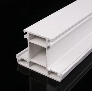
5.5.1 Main profile
“When tested in accordance with EN 479 for each test specimen the heat reversion (R) of the two largest opposing sight surfaces shall not be > 2,0 %.
The difference in heat reversion for each test specimen between these sight surfaces shall not be > 0,4 %.
5.5.2 Auxiliary profiles
When tested in accordance with EN 479 the heat reversion for each test specimen shall not be > 3,0 %.
Note: For glazing beads which are to be used externally a limit of 2 % of the heat reversion is recommended.
5.6 Resistance to impact of main profiles by falling mass
When tested in accordance with EN 477 for the appropriate classification no more than one test specimen shall show rupture in the wall.
For coextruded profiles the delamination of the coextruded layer is also considered as failure.
5.7 Behaviour after heating at 150 °C
When tested in accordance with EN 478 the profiles shall show no defects. For coextruded profiles the delamination of the coextruded layer is also considered as failure.
5.8 Resistance to weathering
5.8.1 Exposure procedure
Test specimens taken from sight surfaces of main profiles shall be exposed in the climatic zone M or S in accordance with EN 513 for a time period representing five years outdoor weathering in terms of the calculation method given in annex B.
In annex C a calculation method is given for the determination of the radiation dose or exposure time to be used for artificial weathering.
Note: For quality control purposes the time period can be decreased to representing two years outdoor exposure.
5.8.2 Impact strength after artificial weathering
After exposure in accordance with 5.8.1 the reduction in impact strength expressed as a percentage of the impact strength of the unexposed test specimens and the exposed test specimens shall not be > 40 %.
The determination of the impact strength is in accordance with EN 513.
Note: The value of 40 % is tentative and subject to the results of current research.
5.8.3 Colour fastness

Note: The visual change in colour can be determined using the methods specified in EN 20105-A02 and EN 20105-A03.
5.9 Weldability

The weld shall not be finished by grooving, knifing etc. except for the outside edge of the 90° angle, which shall be cleaned to permit the sample to sit fully onto the support.
Annex A
(normative)
Material characteristics, preparation of samples and requirements
A.1 Scope
Annex A describes a procedure to prepare samples from PVC-U profiles or from granules or powder from virgin, re-processable or recyclable material for the determination of the characteristics and the requirements for those characteristics.
A.2 Test specimens
The test specimens for the determination of the material characteristics according A.4 shall be taken either from profiles or from pressed plaques.
A.3 Preparation of pressed plaques
The preparation of the pressed plaques shall be in accordance with the procedure given in clause 3 of EN ISO 1163-2:1999 and with the following:
— the material used shall be shredded extruded PVC-U profiles, granules or powder from virgin, reprocessable or recyclable materials;
— the differential speed between the two rolls of the mixing mill shall be within the range 1 : 1,4 to 1 : 1,1; the pressed plaque shall have a thickness of (4 ± 0,2) mm;
— the cooling of the plaque given in 3.3.3 of EN ISO 1163-2:1999 shall be at the nominal rate of 15 K/min.
A.4 Material characteristics
A.4.1 Vicat softening temperature
When tested in accordance with EN ISO 306 using method B with a temperature rate of (50 ± 5) °C/h the Vicat Softening Temperature (VST) shall not be < 75 °C.
For non-coextruded profiles the test specimens shall be taken directly from the profiles or from pressed plaques.
For coextruded profiles the test specimens shall be taken from pressed plaques made from materials separately.
In case of dispute the test on pressed plaques is the reference method.
A.4.2 Charpy impact strength
When tested in accordance with EN ISO 179-2 at (23 ± 2) °C with method designation 1eA the Charpy impact strength shall either not be < 10 kj/m2 or < 20 kj/m2. The level chosen shall be specified by the manufacturer.
For non-coextruded profiles the test specimens shall be taken from pressed plaques.
For coextruded profiles the test specimens shall be taken from pressed plaques made from both materials separately. In case of dispute the test on pressed plaques is the reference method.
A.4.3 Flexural modulus of elasticity
When tested at (23 ± 2) °C in accordance with EN ISO 178 the flexural modulus of elasticity (Eb) shall not be < 2 200 N/mm2.
For non-coextruded profiles the test specimens shall be taken directly from the profiles or from pressed plaques.
For coextruded profiles the test specimens shall be taken from pressed plaques made from both materials separately. In case of dispute the test on pressed plaques is the reference method.
A.4.4 Tensile impact strength
When tested at (23 ± 2) °C in accordance with EN ISO 8256, using type 5 test specimens, the mean tensile impact strength shall be not < 600 kj/m2.
For non-coextruded as well as coextruded profiles the test specimens shall be taken directly from the profiles.
Annex B
(informative)
Permissible tolerances on standard coIour
B.1 Scope
Annex B gives an advice on permissible tolerances on standard colour.
B.2 Permissible tolerances on standard colour
When determined in accordance with ISO 7724-3 with the apparatus in accordance with ISO 7724-1 and ISO 7724-2 with the following specifications:
— employing CIE Standard illuminant D65 including specular reflectance;
— measuring condition 8/d or d/8 (without gloss trap for both);
it is advisable that no profile should have a difference in colour to the standard colour by more than the following limits:
|AL*|<1,0
|Aa*| <0,5
|Ab*| <0,8
|AE*|<1,0
Annex C (normative)
Calculation method for the determination of the radiation dose and exposure time to be used for artificial weathering
C.1 Scope
Annex C describes a procedure to calculate the duration of the exposure needed to assess resistance to moderate (M) and severe (S) climates to be used for artificial weathering.
A justification for the chosen method is included in this annex.
C.2 Calculation
C.2.1 In 4.1 the climatic zones are classified in terms of the annual solar energy falling on a horizontal surface and the average temperature of the warmest month per year (see Table I).
C.2.2 For the purpose of this calculation the following assumption is made on the annual solar energy:
— for moderate climate the amount of solar energy is estimated at 4 Gj/m2/year;
— for severe climate the amount of solar energy is estimated at 6 Gj/m2/year.
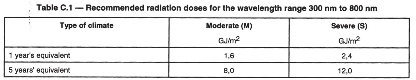
C.2.3 In order to compare these figures with the usual practice in artificial weathering, it is necessary to consider not the total solar radiation energy as in C.2.2, but that part falling in the ultraviolet and visible regions between 300 nm to 800 nm. This is about 60 % of the total solar radiation energy. A further correction factor of 67 % is applied to allow for the fact, that not all this radiation is acting at higher summer temperatures and so will be less damaging to the effected surfaces.
The recommended radiation doses for the wavelength range between 300 nm to 800 nm are given in Table C.1.
C.2.4 For an artificial weathering device having a time-averaged irradiance of ] W/m2 in the range 300 nm to 800 nm the exposure times are given in Table C.2.
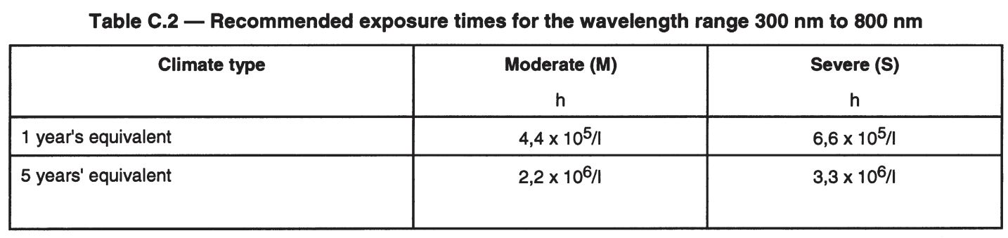
Where I = 550 W/m2, this means for 5 years’ equivalent radiation, then the following exposure time is needed:
— for a moderate climate (M): an exposure time of ca. 4 000 h;
— for a severe climate (S): an exposure time of ca. 6 000 h.
NOTE This calculation method represents only approximate means of estimation. However, it does put the requirements on some sort of logical basis bearing in mind that natural weathering itself is a variable phenomenon depending on location, aspect, shading etc.
-
 Falling Weight Impact Tester-OD:1200-H:2000mm
 -
 Tensile-Compression Universal Tester (250KN) Servomotor Controlled
 -
Tensile-Compression Universal Tester (200KN) Servomotor Controlled-900mm Column Distance
-
 CNC Milling for Tensile Sample Preparation-Max80mm
 -
 Tensile Compression Tester 100KN-Column distance 1000mm – Travel 1500mm
 -
Falling Weight Impact Tester Accoriding to ISO 13957-OD:250-H:2000mm
-
Tensile-Compression Universal Tester (300KN) Servomotor Controlled
-
 Pendulum Impact Tester (Charpy-50)-(Izod-22J)
 -
Pendulum Impact Tester (Charpy)- 15J
-
Falling Weight Impact Tester-OD:630-H:2000mm
-
Ring Stiffness Tester According to ISO 9969-100KN-630mm
-
Ring Stiffness Tester According to ISO 9969-50KN-630mm
-
 Single Column Tensile Compression Tester (UTM)-50 Kg-1000mm
 -
Single Column Tensile Compression Tester (UTM)-100 Kg-1000mm
-
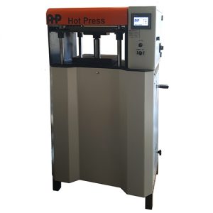 Hot Press (Hydraulic Type)-500KN-400 x 400mm Plate-190mm Stroke
 -
Ring Stiffness Tester According to ISO 9969-50KN-2000mm
-
Box Compression Tester-20KN (100Kg Loadcell)-650mm-200*400 Plate
-
Pendulum Impact Tester (Izod, Charpy, Tensile Impact)- AHP50P-(22,25,15j)
-
Falling Weight Impact Tester-OD:400-H:2000mm
-
 Welding Strength Tester for UPVC Profiles-20KN
 -
Tensile-Compression Universal Tester (100KN) Servomotor Controlled
-
 Tensile Grips Type 3-ISO 6259
 -
Pendulum Impact Tester (IZOD)- 15J
-
Tensile-Compression Universal Tester (200KN) Servomotor Controlled