9.1 Type tests and test sequences
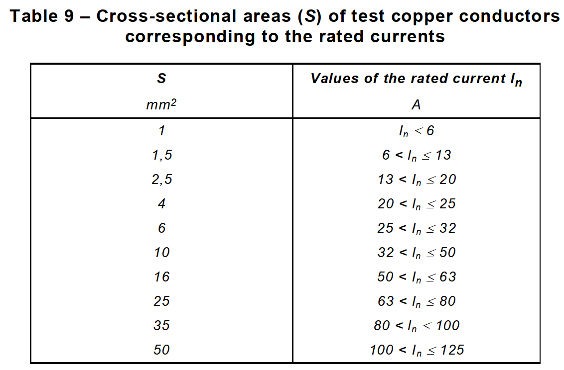
9.1.1 The characteristics of circuit-breakers are verified by means of type tests. Type tests required by this standard are listed in table 8.
9.2 Test conditions
The circuit-breaker is mounted individually, vertically and in free air at an ambient temperature between 20 °C and 25 °C, unless otherwise specified, and is protected against undue external heating or cooling.
Circuit-breakers designed for installation in an individual enclosure are tested in the smallest of such enclosures specified by the manufacturer.
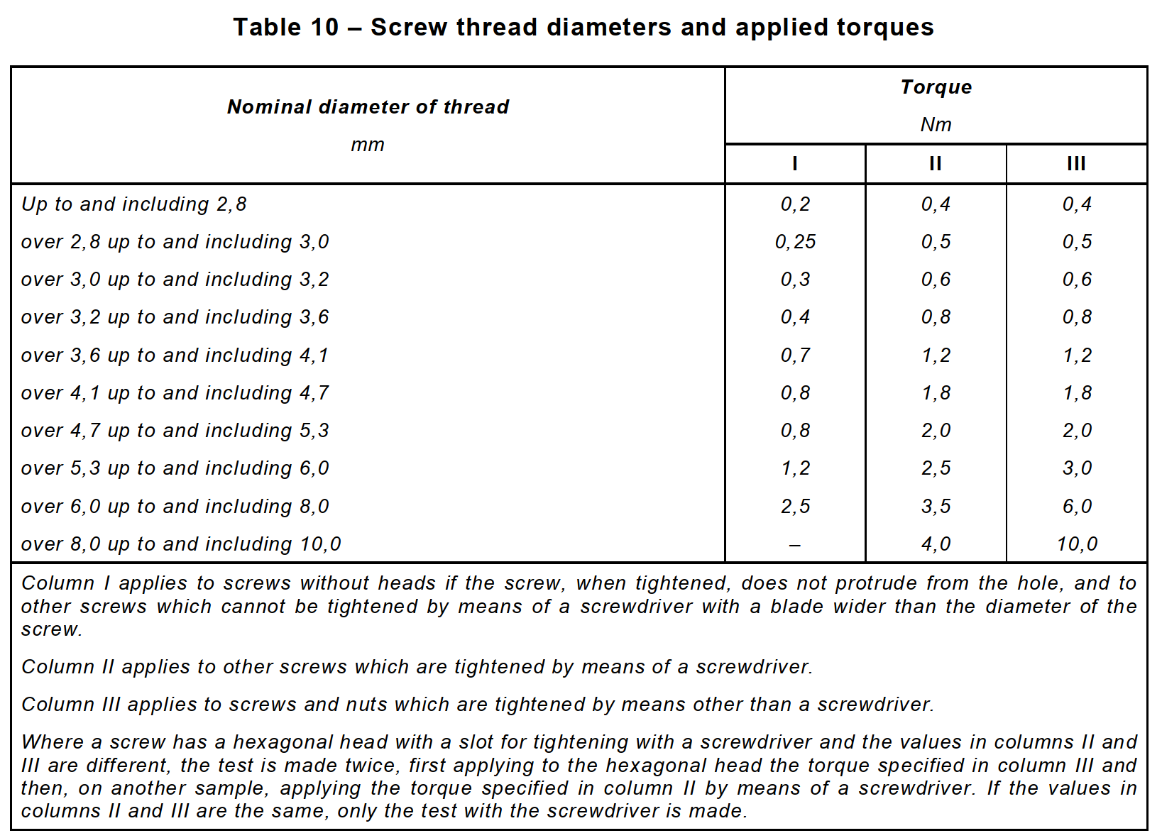
Unless otherwise specified, the circuit-breakers are wired with the appropriate cable specified in table 9 and are fixed on a dull, black-painted plywood board of about 20 mm thickness, the method of fixing complying with any requirements relating to the means of mounting recommended by the manufacturer.
Where a tolerance is not specifically specified, type tests are carried out at values not less severe than those specified in this standard.
Unless otherwise specified, tests are carried out at the rated frequency ±5 Hz and at any convenient voltage.
During the tests, no maintenance or dismantling of the samples is allowed.
For the tests of 9.8, 9.9, 9.10 and 9.11 the circuit-breaker is connected as follows.
a)The connections are made by means of single-core, PVC insulated copper cables, according to IEC 60227.
b)The tests are carried out with single-phase current, with all poles connected in series, except for the tests of 9.8.2, 9.10.2 and 9.11.
c)The connections are in free air and spaced not less than the distance between the terminals.
d)The minimum length of each temporary connection from terminal to terminal is:
– 1 m for cross-sections up to and including 10 mm2;
– 2 m for cross-sections larger than 10 mm2.
The tightening torques to be applied to the terminal screws are two-thirds of those specified in table 10.
9.3 Test of indelibility of marking
The test is made by rubbing the marking by hand for 15 s with a piece of cotton soaked with water and again for 15 s with a piece of cotton soaked with aliphatic solvent hexane with a content of aromatics of maximum 0,1 % by volume, a kauributanol value of 29, an initial boiling-point approximately 65 °C, a dry-point of approximately 69 °C and a density of approximately 0,68 g/cm³.
Marking made by impression, moulding, or engraving is not subjected to this test.
After this test, the marking shall be easily legible.
The marking shall also remain easily legible after all the tests of this standard.
It shall not be easily possible to remove labels and they shall show no curling.
9.4 Test of reliability of screws, current-carrying parts and connections
Compliance with the requirements of 8.1.4 is checked by inspection and, for screws and nuts which are operated when mounting and connecting up the circuit-breaker, by the following test.
The screws or nuts are tightened and loosened
– ten times for screws in engagement with a thread of insulating material;
– five times in all other cases.
Screws or nuts in engagement with a thread of insulating material are completely removed and reinserted each time.
The test is made by means of a suitable test screwdriver or spanner applying a torque as shown in table 10.
The screws and nuts shall not be tightened in jerks.
The conductor is moved each time the screw or nut is loosened.
Plug-in connections are tested by plugging the circuit-breaker in and pulling it out five times. After the test the connections shall not have become loose nor shall their electrical function
be impaired.
During the test, the screwed connections shall not work loose and there shall be no damage, such as breakage of screws or damage to the head slots, threads, washers or stirrups, that will impair the further use of the circuit-breaker.
Moreover, enclosures and covers shall not be damaged.
Plug-in connections are tested by plugging the circuit-breaker in and pulling it out five times. After the test the connections shall not have become loose nor shall their electrical function
be impaired.
9.5 Tests of reliability of screw-type terminals for external copper conductors
Compliance with the requirements of 8.1.5 is checked
–by inspection, by the test of 9.4, where a rigid copper conductor having the largest cross-sectional area specified in table 5 is placed in the terminal (for nominal cross-sectional areas exceeding 6 mm², a rigid stranded conductor is used while for other nominal cross-sectional areas, a solid conductor is used);
–by the tests of 9.5.1, 9.5.2 and 9.5.3. These last tests are made by means of a suitable screwdriver or spanner applying a torque as shown in table 10.
9.5.1 The terminals are fitted with copper conductors of the smallest and largest cross-sectional areas specified in table 5, solid or stranded, whichever is the most unfavourable.
The conductor is inserted into the terminal for the minimum distance prescribed or, where no distance is prescribed, until it just projects from the far side, and in the position most likely to assist the wire to escape.
The clamping screws are then tightened with a torque equal to two-thirds of that shown in the appropriate column of table 10.
Each conductor is then subjected to a pull of the value, in newtons, shown in table 11. The pull is applied without jerks, for 1 min, in the direction of the axis of the conductor space.
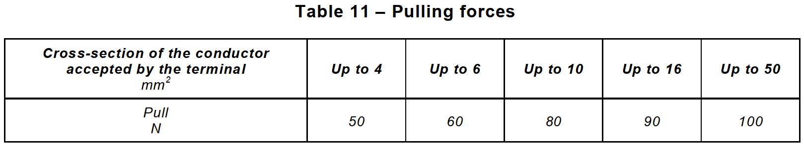
During the test, the conductor shall not move noticeably in the terminal.
9.5.2 The terminals are fitted with copper conductors of the smallest and largest cross-sectional areas specified in table 5, solid or stranded, whichever is the most unfavourable, and the terminal screws are tightened with a torque equal to two-thirds of that shown in the appropriate column of table 10. The terminal screws are then loosened and the part of the conductor which may have been affected by the terminal is inspected.
The conductors shall show no undue damage nor severed wires.
NOTE Conductors are considered to be unduly damaged if they show deep and sharp indentations.
During the test, terminals shall not work loose and there shall be no damage, such as breakage of screws or damage to the head slots, threads, washers or stirrups, that will impair the further use of the terminal.
9.5.3 The terminals are fitted with a rigid stranded copper conductor having the make-up shown in table 12.
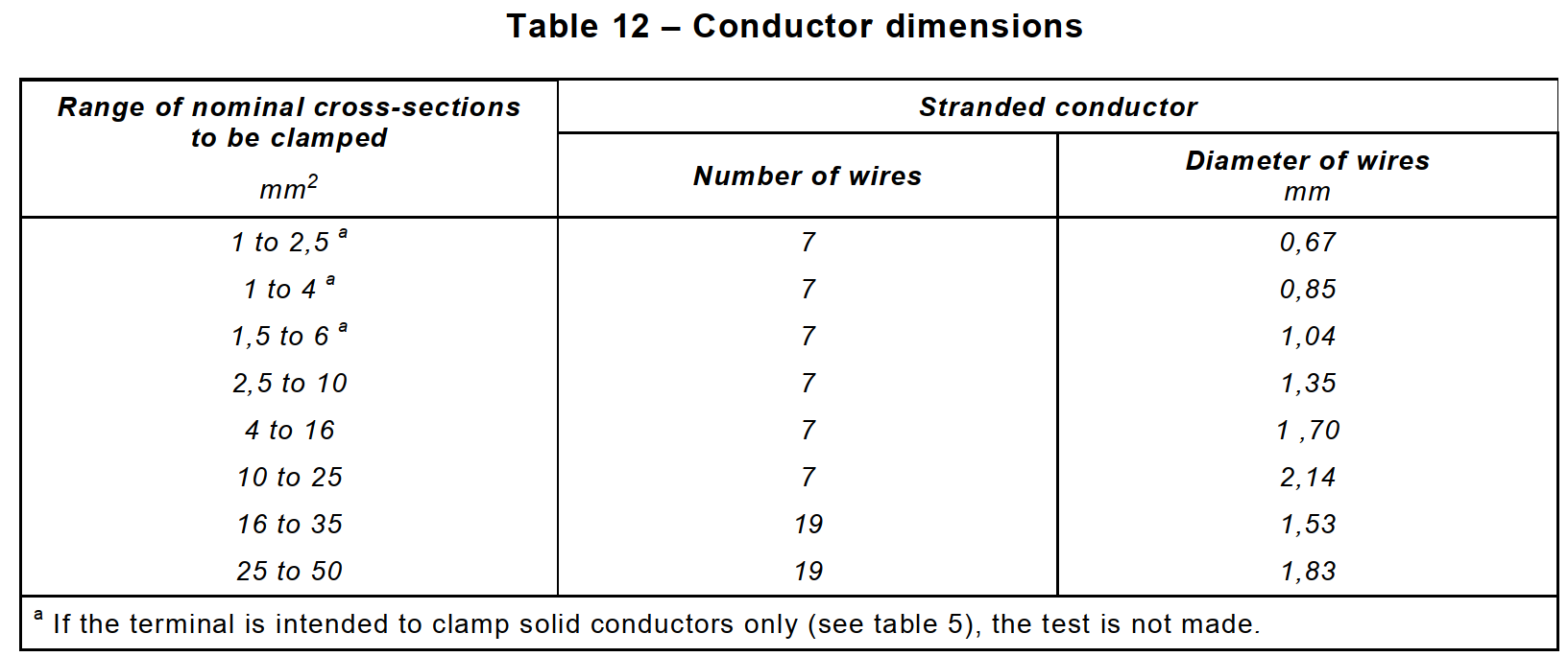
Before insertion into the terminal, the wires of the conductors are suitably reshaped.
The conductor is inserted into the terminal until the conductor reaches the bottom of the terminal or just projects from the far side of the terminal and in the position most likely to assist a wire to escape. The clamping screw or nut is then tightened with a torque equal to two-thirds of that shown in the appropriate column of table 10.
After the test, no wire of the conductor shall have escaped from the clamping unit.
9.6 Test of protection against electric shock
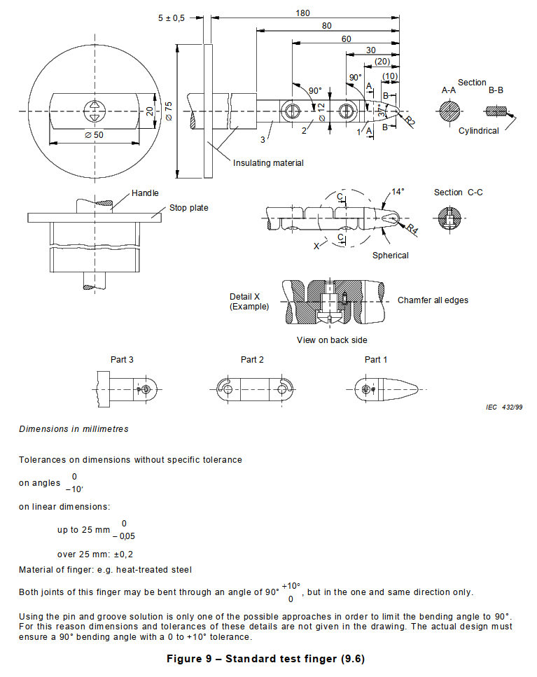
The test is made with the standard test finger shown in figure 9, on the sample mounted as for normal use (see note to 8.1.6) and fitted with the conductors of the smallest and largest cross-sectional areas specified in table 5.
The standard test finger shall be so designed that each of the jointed sections can be turned through an angle of 90° with respect to the axis of the finger, in the same direction only.
The test finger is applied in every possible bending position of a real finger, an electrical contact indicator being used to show contact with live parts.
It is recommended that a lamp be used for the indication of contact and that the voltage be not less than 40 V.
Circuit-breakers with enclosures or covers of thermoplastic material are subjected to the following additional test, which is carried out at an ambient temperature of 35 °C ± 2 °C, the circuit-breakers being at this temperature.
The circuit-breakers are subjected for 1 min to a force of 75 N, applied through the tip of a straight unjointed test finger of the same dimensions as the standard test finger. This finger is applied to all places where yielding of insulating material could impair the safety of the circuit-breaker, but is not applied to knock-outs.
During this test, enclosures or covers shall not deform to such an extent that live parts can be touched with the unjointed test finger.
Unenclosed circuit-breakers having parts not intended to be covered by an enclosure are submitted to the test with a metal front panel, and mounted as for normal use (see 8.1.6).
9.7 Test of dielectric properties and isolating capability
9.7.1 Resistance to humidity
9.7.1.1 Preparation of the circuit-breaker for test
Inlet openings, if any, are left open; if knock-outs are provided, one of them is opened.
Parts which can be removed without the aid of a tool are removed and subjected to the humidity treatment with the main part; spring lids are kept open during this treatment.
9.7.1.2 Test conditions
The humidity treatment is carried out in a humidity cabinet containing air with a relative humidity maintained between 91 % and 95 %.
The temperature of the air in which the sample is placed is maintained within ±1 °C of any convenient value T between 20 °C and 30 °C.
Before being placed in the humidity cabinet, the sample is brought to a temperature between T and T +4 °C.
9.7.1.3 Test procedure
The sample is kept in the cabinet for 48 h.
NOTE 1 A relative humidity between 91 % and 95 % can be obtained by placing in the humidity cabinet a saturated solution of sodium sulphate (Na2SO4) or potassium nitrate (KNO3) in water having a sufficiently large contact surface with the air.
NOTE 2 In order to achieve the specified conditions within the cabinet it is recommended to ensure constant circulation of the air within and, in general, to use a cabinet which is thermally insulated.
9.7.1.4 Condition of the circuit-breaker after the test
After this treatment, the sample shall show no damage within the meaning of this standard and shall withstand the tests of 9.7.2 and 9.7.3.
9.7.2 Insulation resistance of the main circuit
The circuit-breaker is treated as specified in 9.7.1. After an interval between 30 min and 60 min following this treatment, the insulation resistance is measured 5 s after application of a d.c. voltage of approximately 500 V, consecutively as follows:
a) with the circuit-breaker in the open position, between each pair of the terminals which are electrically connected together when the circuit-breaker is in the closed position, on each pole in turn;
b) with the circuit-breaker in the closed position, between each pole in turn and the others connected together;
c) with the circuit-breaker in the closed position, between all poles connected together and the frame, including a metal foil in contact with the outer surface of the internal enclosure of insulating material, if any;
d) between metal parts of the mechanism and the frame;
NOTE – For this verification, specially prepared samples may be used.
e) for circuit-breakers with a metal enclosure having an internal lining of insulating material, between the frame and a metal foil in contact with the inner surface of the lining of insulating material including bushings and similar devices.
The measurements a), b) and c) are carried out after having connected all auxiliary circuits to the frame.
The term “frame” includes:
– all accessible metal parts and a metal foil in contact with the surfaces of insulating material which are accessible after installation as for normal use;
– the surface on which the base of the circuit-breaker is mounted, covered, if necessary, with a metal foil;
– screws and other devices for fixing the base to its support;
– screws for fixing covers which have to be removed when mounting the circuit-breaker, and metal parts of operating means referred to in 8.2.
If the circuit-breaker is provided with a terminal intended for the interconnection of protective conductors, this terminal is connected to the frame.
For the measurements according to items b) to e), the metal foil is applied in such a way that the sealing compound, if any, is effectively tested.
The insulation resistance shall be not less than
– 2 M Ω for the measurements according to items a) and b);
– 5 M Ω for the other measurements.
9.7.3 Dielectric strength of the main circuit
After the circuit-breakers have passed the tests of 9.7.2 the test voltage specified in 9.7.5 is applied for 1 min between the parts indicated in 9.7.2.
Initially, not more than half the prescribed voltage is applied, then it is raised to the full value within 5 s.
No flashover or breakdown shall occur during the test.
Glow discharges without drop in the voltage are neglected.
9.7.4 Dielectric strength of the auxiliary and control circuits
For these tests, the main circuit shall be connected to the frame. The test voltage specified in
9.7.5 shall be applied for 1 min as follows:
a)between all the auxiliary and control circuits, which are not normally connected to the main circuit, connected together, and the frame of the circuit-breaker;
b)where appropriate, between each part of the auxiliary and control circuits which may be isolated from the other parts of the auxiliary circuits and these other parts connected together.
9.7.5 Value of test voltage
The test voltage shall have practically sinusoidal waveform, and a frequency between 45 Hz and 65 Hz.
The source of the test voltage shall be capable of supplying a short-circuit current of at least 0,2 A.
No overcurrent tripping device of the transformer shall operate when the current in the output circuit is lower than 100 mA.
The values of the test voltage shall be as follows:
a)for the main circuit, for auxiliary circuits intended to be connected to the main circuit and for control circuits:
– 2 000 V for items a) to d) of 9.7.2;
– 2 500 V for item e) of 9.7.2;
b)for auxiliary and control circuits which are indicated by the manufacturer as unsuitable for connection to the main circuit:
–1 000 V, where the rated insulation voltage Ui does not exceed 60 V;
–2 Ui + 1 000 V, with a minimum of 1 500 V, where the rated insulation voltage Uiexceeds 60 V.
9.7.6 Verification of impulse withstand voltages (across clearances and across solid insulation) and of leakage current across open contacts
9.7.6.1 Verification of impulse withstand voltage across the open contacts (suitability for isolation)
The test is carried out on a circuit-breaker fixed on a metal support.
The impulses are given by a generator producing positive and negative impulses having a front time of 1,2 µs, and a time to half-value of 50 µs, the tolerances being
– ±5 % for the peak value;
– ±30 % for the front time;
– ±20 % for the time to half-value.
The surge impedance of the test apparatus shall have a nominal value of 500 Ω.
The shape of the impulses is adjusted with the circuit-breaker under test connected to the impulse generator. For this purpose appropriate voltage dividers and voltage sensors shall be used.
Small oscillations in the impulses are allowed provided that their amplitude near the peak of the impulse is less than 5 % of the peak value.
For oscillations on the first half of the front, amplitudes up to 10 % of the peak value are allowed.
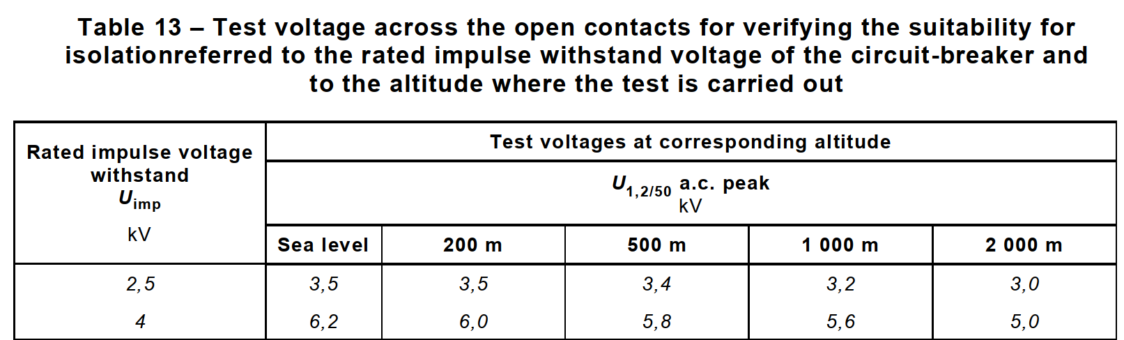
The 1,2/50 µs impulse voltage according to figure 6 of IEC 60060-1 is applied between the line terminals connected together and the load terminals connected together with the contacts in the open position.
Three positive impulses and three negative impulses are applied, the interval between consecutive impulses being at least 1 s for impulses of the same polarity and being at least 10 s for impulses of the opposite polarity.
The test impulse voltage values shall be chosen in table 13, in accordance with the rated impulse voltage of the circuit-breaker as given in table 3. These values are corrected for barometric pressure and/or altitude at which the tests are carried out, according to table 13.
There shall be no unintentional disruptive discharges during the test.
9.7.6.2 Verification of impulse withstand voltage for the parts not tested in 9.7.6.1
The test is carried out on a circuit-breaker fixed on a metal support being in the closed position.
The impulses are given by a generator producingpositive and negative impulses having a front time of 1,2 µs and a time to half value of 50 µsthe tolerances being
– ±5 % for the peak value;
– ±30 % for the front time;
– ±20 % for the time to half value.
The surge impedance of the test apparatus shall have a nominal value of 500 Ω
.
The shape of the impulses is adjusted with the circuit-breaker under test connected to the impulse generator. For this purpose appropriate voltage dividers and voltage sensors shall be used.
NOTE 1 For circuit-breakers with incorporated surge arresters the shape of the impulses is adjusted without connection of the circuit-breaker to the impulse generator.
Small oscillations in the impulses are allowed, provided that their amplitude near the peak of the impulse is less than 5 % of the peak value.
For oscillations on the first half of the front, amplitudes up to 10 % of the peak value are allowed.
A first series of tests is made applying the impulse voltage between the phase pole(s), connected together, and the neutral pole (or path) of the circuit-breaker, as applicable.
A second series of tests is made applying the impulse voltage between the metal support connected to the terminal(s) intended for the protective conductor(s), if any, and the phase pole(s) and the neutral pole (or path) connected together.
In both cases three positive impulses and three negative impulses are applied, the interval between consecutive impulses being at least 1 s for impulses of the same polarity and at least 10 s for impulses of the opposite polarity.
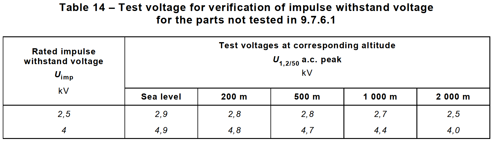
The test impulse voltage values shall be chosen in table 14 in accordance with the rated impulse voltage of the circuit-breaker as given in table 3. These values are corrected for barometric pressure and/or altitude at which the tests are carried out, according to table 14.
There shall be no flashover nor unintentional disruptive discharges during the test.
If, however, only one such disruptive discharge occurs, six additional impulses having the same polarity as that which caused the disruptive discharge are applied, the connections being the same as those with which the failure occurred.
No further disruptive discharge shall occur.
9.7.6.3 Verification of leakage currents across open contacts
(suitability for isolation)
Each pole of circuit-breakers having been submitted to the tests of 9.12.11.2, or 9.12.11.3, or
9.12.11.4.2 or 9.12.11.4.3 is supplied at a voltage 1.1 times its rated operational voltage, the circuit-breaker being in the open position.
The leakage current flowing across the open contacts is measured and shall not exceed 2 mA.
9.8 Test of temperature-rise and measurement of power loss
9.8.1 Ambient air temperature
The ambient air temperature shall be measured during the last quarter of the test period by means of at least two thermometers or thermocouples symmetrically positioned around the circuit-breaker at about half its height and at a distance of about 1 m from the circuit-breaker.
The thermometers or thermocouples shall be protected against draughts and radiant heat.
9.8.2 Test procedure
A current equal to In at any convenient voltage is passed simultaneously through all the poles of the circuit-breaker for a period of time sufficient for the temperature-rise to reach the steady-state value or for the conventional time, whichever is the longer.
In practice, this condition is reached when the variation of the temperature-rise does not exceed 1 K/h.
For four-pole circuit-breakers with three protected poles, the test is first made by passing the specified current through the three protected poles only.
The test is then repeated by passing the same current through the pole intended for the connection of the neutral and the adjacent protected pole.
During the test, the temperature-rises shall not exceed the values shown in table 6.
9.8.3 Measurement of the temperature of parts
The temperature of the different parts referred to in table 6 shall be measured by means of fine wire thermocouples or by equivalent means at the nearest accessible position to the hottest spot.
Good heat conductivity between the thermocouple and the surface of the part under test shall be ensured.
9.8.4 Temperature-rise of a part
The temperature-rise of a part is the difference between the temperature of this part measured in accordance with 9.8.3, and the ambient air temperature measured in accordance with 9.8.1.
9.8.5 Measurement of power loss
An a.c. current equal to In, with a supply voltage of a value not less than 30 V, is passed, in a substantially resistive circuit, through each pole of the circuit-breaker.
NOTE 1 A test voltage of a value less than 30 V may be used subject to the manufacturer’s agreement.
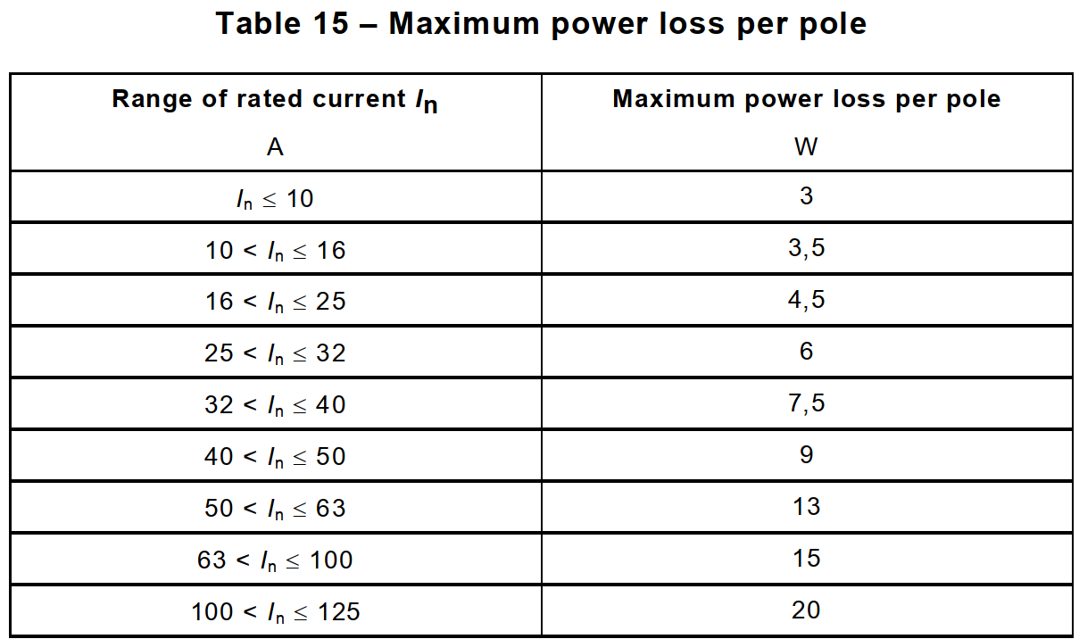
The power loss per pole, calculated on the basis of the voltage drop measured under steady state conditions between its terminals, shall not exceed the relevant values given in table 15.
NOTE 2 The voltage drop measurement may be made during the temperature-rise test, provided that the test conditions of this subclause are fulfilled.
9.9 28-day test
The circuit-breaker is subjected to 28 cycles, each cycle comprising 21 h with a current equal to the rated current at an open circuit voltage of at least 30 V, and 3 h without current under the test conditions of 9.2.
The circuit-breaker is in the closed position, the current being established and interrupted by an auxiliary switch. During this test the circuit-breaker shall not trip.
During the last period of current flow the temperature-rise of the terminals shall be measured. This temperature-rise shall not exceed the value measured during the temperature-rise test
(see 9.8) by more than 15 K.
Immediately after this measurement of the temperature-rise, the current is steadily increased within 5 s to the conventional tripping current.
The circuit-breaker shall trip within the conventional time.
9.10 Test of tripping characteristic
This test is made to verify that the circuit-breaker complies with the requirements of 8.6.1.
9.10.1 Test of time-current characteristic
9.10.1.1 A current equal to 1,13 In (conventional non-tripping current) is passed for the conventional time (see 8.6.1 and 8.6.2.1) through all poles, starting from cold (see table 7).
The circuit-breaker shall not trip.
The current is then steadily increased within 5 s, to 1,45 In (conventional tripping current).
The circuit-breaker shall trip within the conventional time.
9.10.1.2 A current equal to 2,55 In is passed through all poles, starting from cold.
The opening time shall not be less than 1 s and shall not be more than
– 60 s for rated currents up to and including 32 A;
– 120 s for rated currents greater than 32 A.
9.10.2 Test of instantaneous tripping and of correct opening of the contacts
9.10.2.1 General test conditions
For the lower values of the test current of 9.10.2.2, 9.10.2.3 and 9.10.2.4 respectively the test is made once, at any convenient voltage.
For the upper values of the test current the test is made at rated voltage Un (phase to neutral) with a power factor between 0,95 and 1.
The sequence of operation is
O-t-CO-t-CO-t-CO
the interval t being as defined in 9.12.11.1.
The tripping time of the O operation is measured.
After each operation the indicating means shall show the open position of the contacts.
9.10.2.2 For circuit-breakers of the B-type
A current equal to 3 In is passed through all poles starting from cold.
The opening time shall not be less than 0,1 s.
A current equal to 5 In is then passed through all poles, again starting from cold.
The circuit-breaker shall trip in a time less than 0,1 s.
9.10.2.3 For circuit-breakers of the C-type
A current equal to 5 In is passed through all poles, starting from cold.
The opening time shall be not less than 0,1 s.
A current equal to 10 In is then passed through all poles, again starting from cold.
The circuit-breaker shall trip in a time less than 0,1 s.
9.10.2.4 For circuit-breakers of the D-type
A current equal to 10 In is passed through all poles, starting from cold.
The opening time shall be not less than 0,1 s.
A current equal to 20 In or to the maximum instantaneous tripping current (see clause 6, item j) is then passed through all poles, again starting from cold.
The circuit-breaker shall trip in a time less than 0,1 s.
9.10.3 Test of effect of single-pole loading on the tripping characteristic of multipole circuit-breakers
Compliance is checked by testing the circuit-breaker connected in accordance with 9.2, under the conditions specified in 8.6.3.1.
The circuit-breaker shall trip within the conventional time (see 8.6.2.1).
9.10.4 Test of effect of ambient temperature on the tripping characteristic
Compliance is checked by the following tests.
a) The circuit-breaker is placed in an ambient temperature of (35 ± 2) K below the ambient
air reference temperature until it has attained steady-state temperature.
A current equal to 1,13 In (conventional non-tripping current) is passed through all poles for the conventional time. The current is then steadily increased within 5 s to 1,9 In.
The circuit-breaker shall trip within the conventional time.
b) The circuit-breaker is placed in an ambient temperature of (10 ± 2) K above the ambient air reference temperature until it has attained steady-state temperature.
A current equal to In is passed through all poles.
The circuit-breaker shall not trip within the conventional time.
9.11 Test of mechanical and electrical endurance
9.11.1 General test conditions
The circuit-breaker is fixed to a metal support unless it is designed for installation in an individual enclosure, in which case it shall be mounted accordingly, as specified in 9.2.
The test is made at rated voltage, at a current adjusted to the rated current by means of resistors and reactors in series, connected to the load terminals.
If air-core reactors are used, a resistor taking approximately 0,6 % of the current through the reactors is connected in parallel with each reactor.
The current shall have substantially sine-wave form and the power factor shall be between 0,85 and 0,9.
For single-pole circuit-breakers and for two-pole circuit-breakers with two protected poles, the metal support is connected to one side of the supply for the first half of the total number of operations and to the other side for the second half.
For two-pole circuit-breakers with one protected pole, the metal support is connected to the neutral of the supply.
For single-pole circuit-breakers with rated voltage 230/400 V the test shall be carried out at the lower voltage value.
The circuit-breaker is connected to the circuit with conductors of the appropriate size indicated in table 9.
9.11.2 Test procedure
The circuit-breaker is submitted to 4 000 operating cycles with rated current.
Each operating cycle consists of a making operation followed by a breaking operation.
For circuit-breakers of rated current up to and including 32 A the operating frequency shall be 240 operating cycles per hour. During each operating cycle, the circuit-breaker shall remain open for at least 13 s.
For circuit-breakers of rated current above 32 A the operating frequency shall be 120 operating cycles per hour. During each operating cycle the circuit-breaker shall remain open for at least 28 s.
The circuit-breaker shall be operated as in normal conditions of use.
Care shall be taken that
– the test apparatus does not damage the circuit-breaker under test;
– the free movement of the operating means of the circuit-breaker under test is not impeded; – the speed of the operating means of the test apparatus is not unduly affected by the
operating means of the circuit-breaker under test.
In case of circuit-breakers with dependent manual operation, the circuit-breaker shall be operated with an operating speed, during actuation, of 0,1 m/s ± 25 %, this speed being measured at the extremity when and where the operating means of the test apparatus touches the actuating means of the circuit-breaker under test. For rotary knobs the angular velocity shall correspond substantially to the above conditions, referred to the speed of the operating means (at its extremities) of the circuit-breaker under test.
9.11.3 Condition of the circuit-breaker after test
Following the test of 9.11.2 the sample shall not show
– undue wear;
– discrepancy between the position of the moving contacts and of the corresponding position of the indicating device;
– damage to the enclosure permitting access to live parts by the test finger (see 9.6);
– loosening of electrical or mechanical connections;
– seepage of sealing compound.
Moreover, the circuit-breaker shall comply with the test of 9.10.1.2 and shall withstand the dielectric strength test according to 9.7.3, but at a voltage 500 V less than the value prescribed in 9.7.5 and without previous humidity treatment.
9.12 Short-circuit tests
9.12.1 General
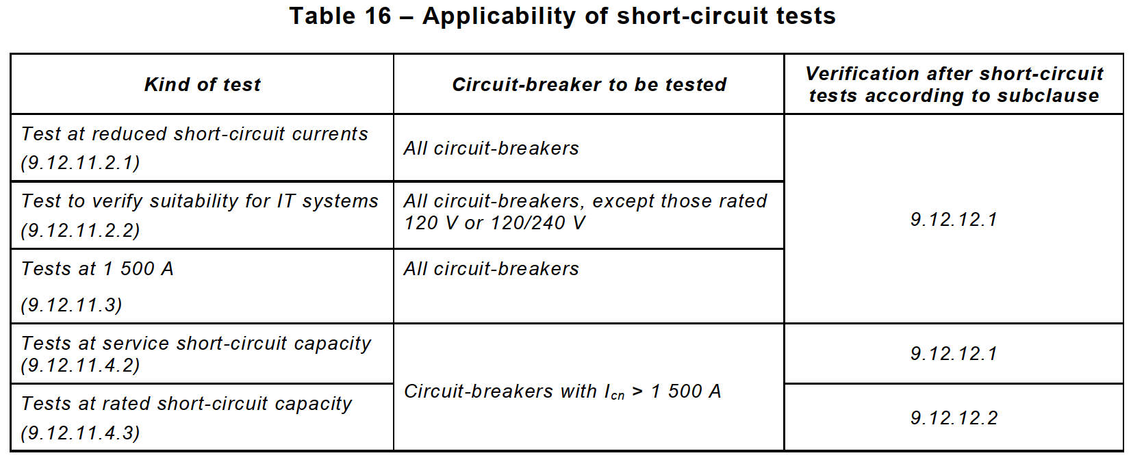
Standard tests for the verification of the short-circuit performance consist of sequences of making and breaking operations, appropriate to the performance to be checked, which are summarized in table 16.
All circuit-breakers are tested at 500 A or 10 In, whichever is the higher, according to
9.12.11.2 and at 1 500 A according to 9.12.11.3.
Circuit-breakers having a rated short-circuit capacity above 1 500 A are additionally tested
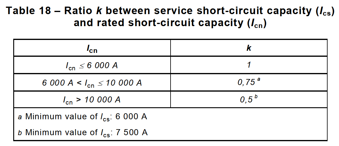
–at service short-circuit (breaking) capacity (see 3.5.5.2) according to 9.12.11.4.2 and 9.12.12.1; the service short-circuit capacity is obtained by multiplying the rated short-circuit capacity by a factor k, the values of which are given in table 18;
– at rated short-circuit capacity (see 5.2.4) according to 9.12.11.4.3 and to 9.12.12.2 if the factor k is less than 1, in which case new samples shall be used.
9.12.2 Values of test quantities
All the tests concerning the verification of the rated short-circuit capacity shall be performed with the values stated by the manufacturer in accordance with the relevant tables of this standard.
The value of the applied voltage is that which is necessary to produce the specified power frequency recovery voltage.
The value of the power frequency recovery voltage (see 3.5.8.2) shall be equal to 105 % of the rated voltage of the circuit-breaker under test.
– For single-pole circuit-breakers having dual rated voltage value (e.g. 230/400 V) the power frequency recovery voltage shall be 105 % of the upper value (e.g. 400 V) for the tests according to item d) of 9.12.11.4.2 , item b of 9.12.11.4.3 and 9.12.11.2.2; it shall be 105 % of the lower value (e.g. 230 V) for the other tests of 9.12.
– For two-pole circuit-breakers having dual rated voltage values (e.g. 120/240 V) the recovery voltage shall be 105 % of the lower value (e.g. 120 V) for the tests according to
9.12.11.2 and 105 % of the upper value (e.g. 240 V) for the other tests of 9.12.
NOTE The value of 105 % (±5 %) of the rated voltage is deemed to cover the effects of the variations of the system voltage under normal service conditions. The upper limit may be increased with the approval of the manufacturer.
9.12.3 Tolerances on test quantities
The tests are considered as valid if the r.m.s. values recorded in the test report differ from the values specified within the following tolerances:
– current +5%
– voltage (including recovery voltage): ±5 %
– frequency ±5 %.
9.12.4 Test circuit for short-circuit performance
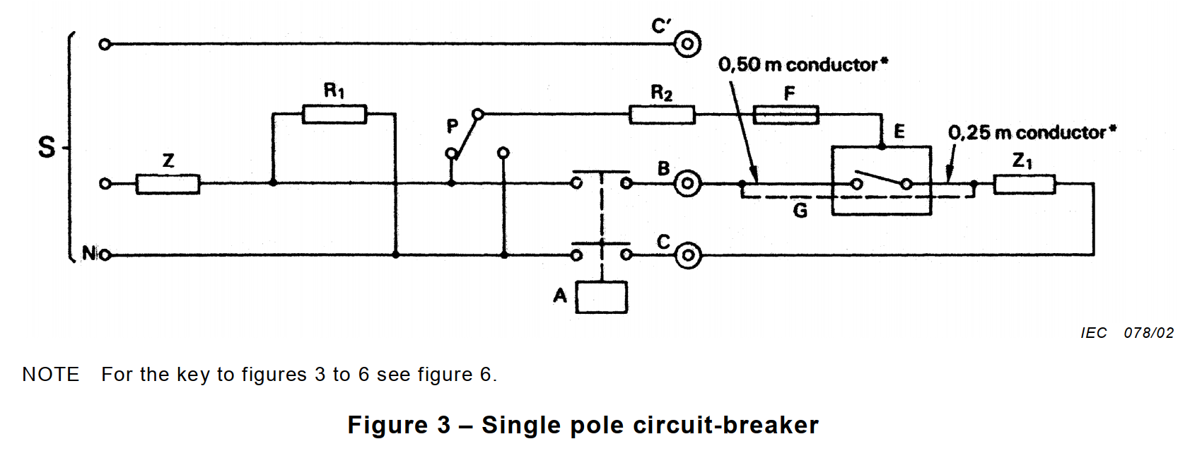
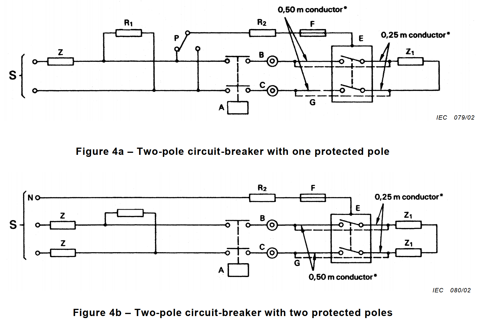
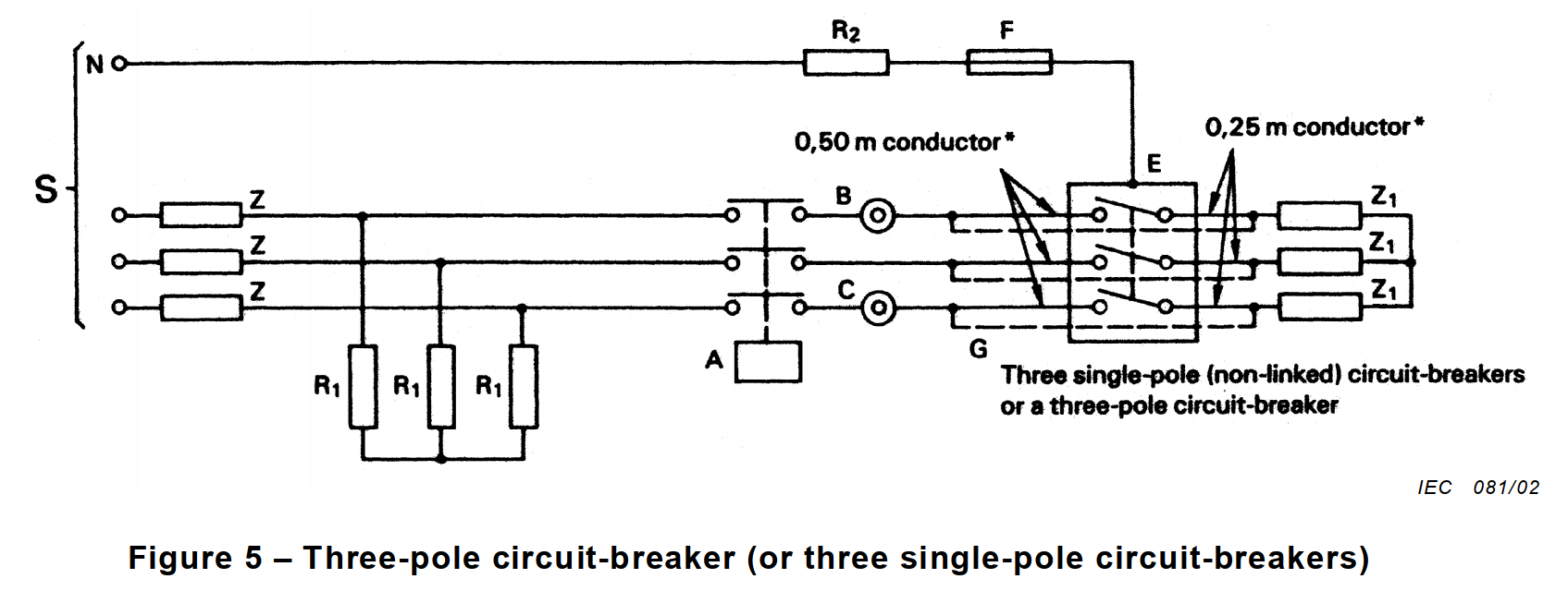
Figures 3 to 6 respectively give the diagrams of the circuits to be used for the tests concerning:
– a single-pole circuit-breaker (figure 3);
– a two-pole circuit-breaker with one protected pole (figure 4a);
– a two-pole circuit-breaker with two protected poles (figure 4b);
– a three-pole circuit-breaker (figure 5);
– a four-pole circuit-breaker (figure 6).
The resistances and reactances of the impedances Z and Z1 shall be adjustable to satisfy the specified test conditions. The reactors shall preferably be air-cored. They shall always be connected in series with the resistors and their value shall be obtained by series coupling of individual reactors; parallel connecting of reactors is permitted when these reactors have practically the same time-constant.
Since the transient recovery voltage (see 3.5.8.1) characteristics of test circuits including air-cored reactors are not representative of usual service conditions, the air-cored reactor in any phase shall be shunted by a resistor taking approximately 0,6 % of the current through the reactor.
If iron-core reactors are used, the iron-core power losses of these reactors shall not exceed the losses that would be absorbed by the resistors connected in parallel with the air-cored reactors.
There shall be one and only one point of the test circuit which is earthed; this may be the short-circuit link of the test circuit or the neutral point of the supply or any other convenient point. In any case the earthing method shall be stated in the test report.
In each test circuit for testing the rated short-circuit capacity, the impedances Z are inserted between the supply source S and the circuit-breaker under test.
When tests are made with current less than the rated short-circuit breaking capacity, the additional impedances Z1, shall be inserted on the load side of the circuit-breaker.
For the tests at both the rated and the service short-circuit capacities, the circuit-breaker shall be connected with cables having a length of 0,75 m per pole and the maximum cross-section corresponding to the rated current according to table 5.
NOTE It is recommended that 0,5 m be connected on the supply side and 0,25 m on the load side of the circuit-breaker under test.
A resistor R2 of about 0,5 Ω is connected in series with a copper wire F as follows:
– for the circuits in figures 3 and 4a, between the metal support and the selector switch P: this switch is in one of its two positions for approximately half the number of operations of the circuit-breaker, and in the other position for the remaining operations;
– for the circuits in figures 4b, 5 and 6, between the metal support and the neutral of the supply.
The copper wire F shall be at least 50 mm in length and
– 0,1 mm in diameter for circuit-breakers to be tested in free air, mounted on a metal support,
– 0,3 mm in diameter for circuit-breakers to be tested in the smallest individual enclosure specified by the manufacturer.
Resistors R1 drawing a current of 10 A per phase are connected on the supply side of the circuit-breaker, between the impedances for adjusting the prospective current to the rated short-circuit capacity of the circuit-breaker.
9.12.5 Power factor of the test circuit
The power factor of each phase of the test circuit shall be determined according to a recognized method which shall be stated in the test report.
Two examples are given in annex A.
The power factor of a polyphase circuit is considered as the mean value of the power factors of each phase.
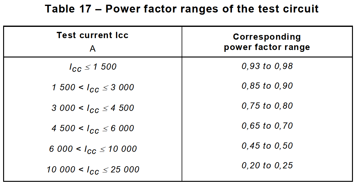
The power-factor ranges are given in table 17.
9.12.6 Measurement and verification of I 2t and of the peak current (Ip)
The I 2t and Ip values shall be measured during the tests of 9.12.11.2, 9.12.11.3 and 9.12.11.4.
In the case of tests of circuit-breakers in three-phase circuits, the I 2t values shall be measured on each pole.
The maximum I 2t values measured shall be recorded in the test report and they shall not exceed the corresponding values of the I 2t characteristic declared by the manufacturer.
9.12.7 Calibration of the test circuit
9.12.7.1 To calibrate the test circuit, links G having negligible impedance compared with that of the test circuit are connected in the positions shown in figures 3 to 6.
9.12.7.2 To obtain a prospective current equal to the rated short-circuit capacity of the circuit-breaker at the corresponding power factor as stated in table 17 impedances Z are inserted on the supply side of the links G.
9.12.7.3 To obtain a test current lower than the rated short-circuit capacity of the circuit-breaker, additional impedances Z1 are inserted on the load side of the links G, as shown in figures 3 to 6.
9.12.8 Interpretation of records
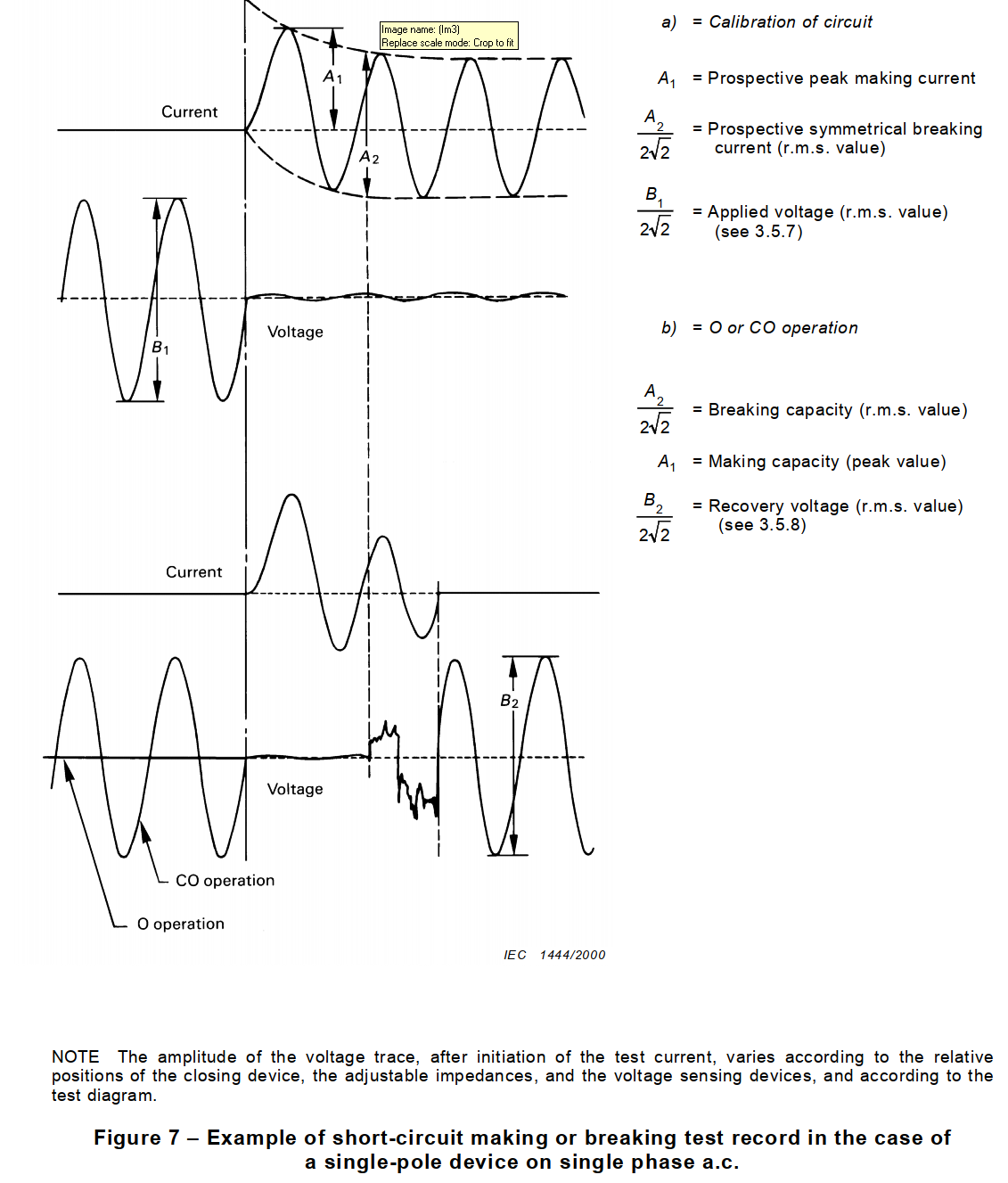
9.12.8.1 Determination of the applied and power frequency recovery voltages
The applied and power frequency recovery voltages are determined from the record corresponding to the opening operation O, (see 9.12.11.1) made with the apparatus under test and estimated as indicated in figure 7. The voltage on the supply side shall be measured during the first cycle after arc extinction in all poles and after high frequency phenomena have subsided.
9.12.8.2 Determination of the prospective short-circuit current
The a.c. component of the prospective current is taken as being equal to the r.m.s. value of the a.c. component of the calibration current (values corresponding to A2 of figure 7).
Where applicable, the prospective short-circuit current shall be the average of the prospective currents in all the phases.
9.12.9 Condition of the circuit-breaker for test
Circuit-breakers shall be tested in free air according to 9.12.9.1, unless they are designed for use only in enclosures specified by the manufacturer or they are intended for use in individual enclosures only, in which cases they shall be tested according to 9.12.9.2 or, with the agreement of the manufacturer, according to 9.12.9.1.
NOTE An individual enclosure is an enclosure designed to accept one device only.
The circuit-breaker shall be operated manually or by means of a test apparatus, simulating as closely as possible the normal closing operation.
Care shall be taken that
– the test apparatus does not damage the circuit-breaker under test;
– the free movement of the operating means of the circuit-breaker under test is not impeded;
– the speed of the operating means of the test apparatus is not unduly affected by the operating means of the circuit-breaker under test.
At the request of the manufacturer, in case of circuit-breakers with dependent manual operation, the circuit-breaker shall be operated with an operating speed, during actuation, of 0,1 m/s ± 25 %, this speed being measured where and when the operating means of the test apparatus touches the operating means of the circuit-breaker under test. For rotary knobs the angular velocity shall correspond substantially to the above conditions, referred to the speed of the operating means (at its extremities) of the circuit-breaker under test.
9.12.9.1 Test in free air
The circuit-breaker under test is mounted as shown in figure H.1.
The polyethylene foil and the barrier of insulating material specified in annex H are placed as shown in figure H.1 for O operations only.
The grid(s) specified in annex H shall be so positioned that the bulk of the emitted ionized gases passes through the grid(s). The grid(s) shall be placed in the most unfavourable position(s).
NOTE If the position of the vents is not obvious, or if there are no vents, appropriate information should be provided by the manufacturer.
The grid circuit(s) (see figure H.3) shall be connected to the points B and C according to the test circuit diagrams of figures 3 to 6; for the test of single-pole circuit-breakers having a rated voltage of 230/400 V the grid circuit(s) shall, however, be connected between phases, to the
points B and C according to the test circuit diagram of figure 3.
The resistor R ′ shall have a resistance of 1,5 Ω. The copper wire F ′ (see figure H.3) shall have a length of 50 mm and a diameter of 0,12 mm for circuit-breakers having a rated voltage of 230 V and 0,16 mm for circuit-breaker having a rated voltage of 400 V or 230/400 V.
For circuit-breakers having a rated voltage of 120 V or 120/240 V the resistor R ′shall have a resistance of 0,75 Ω and the copper wire shall have a diameter of 0,12 mm.
For test currents up to and including 1 500 A, the distance “a” shall be 35 mm.
For higher short-circuit currents up to Icn, the distance “a” may be increased, in which case it shall be chosen from the series (40 – 45 – 50 – 55 – …) mm and stated by the manufacturer.
For test currents greater than 1 500 A any additional barriers or insulating means which allow a shorter distance “a” shall also be stated by the manufacturer.
9.12.9.2 Test in enclosures
The test shall be performed with the circuit-breaker placed in an enclosure having the most unfavourable configuration under the most unfavourable conditions. The grid and the barrier of insulating material shown in figure H.1 are omitted.
NOTE This means that if other circuit-breakers (or other devices) are normally mounted in the direction(s) in which the grid(s) would be placed, these circuit-breakers (or other devices) should be installed there. They should
be supplied as in normal use, but via F′ and R′ as defined in 9.12.9.1, and connected as shown in the appropriate figure (3, 4a, 4b, 5 or 6).
In accordance with the manufacturer’s instructions, barriers or other means, or adequate clearances may be necessary to prevent ionized gases from affecting the installation.
The polyethylene foil as described in annex H is placed as shown in figure H.1 at a distance of 10 mm from the operating means, for O operations only.
9.12.10 Behaviour of the circuit-breaker during short-circuit tests
During the operating sequence of 9.12.11.2 or 9.12.11.3 or 9.12.11.4 the circuit-breaker shall not endanger the operator and shall permit reclosing after the time t as specified in 9.12.11.1, without removing it from the test arrangement.
The polyethylene foil shall show no holes visible with normal or corrected vision without additional magnification.
Furthermore, there shall be no permanent arcing, no flashover between poles or between poles and frame, no melting of the fuse F and , where applicable, of the fuse F .
9.12.11 Test procedure
9.12.11.1 General
The test procedure consists of a sequence of operations.
The following symbols are used for defining the sequence of operations:
O represents an opening operation;
CO represents a closing operation followed by an automatic opening;
t represents the time interval between two successive short-circuit operations which shall be 3 min or such longer time as may be required by the thermal overcurrent release in order to permit the reclosing of the circuit-breaker. This longer time shall be indicated by the manufacturer.
The actual value of t shall be stated in the test report. If the sample does not allow reclosing after the time indicated by the manufacturer it is considered as having failed the test.
After arc extinction, the recovery voltage shall be maintained for a duration not less than 0,1 s.
9.12.11.2 Tests at reduced short-circuit currents
9.12.11.2.1 Test on all circuit-breakers
The additional impedances Z1 (see 9.12.7.3) are adjusted so as to obtain a current of 500 A or 10 times In, whichever is the higher, at a power factor between 0,93 and 0,98.
Each of the protected poles of the circuit-breaker is subjected separately to a test in a circuit the connections of which are shown in figure 3.
The circuit-breaker is caused to open automatically nine times, the circuit being closed six times by the auxiliary switch A and three times by the circuit-breaker itself.
The sequence of operations shall be
O – t – O – t – O – t – O – t – O – t- O – t – CO – t – CO – t – CO
For the test the auxiliary switch A is synchronized with respect to the voltage wave so that the
six points of initiation for the opening operations are equally distributed over the half-wave with a tolerance of ±5°.
9.12.11.2.2 Short-circuit test on circuit-breakers rated 230 V, or 240 V or 230/400 V for verifying their suitability for use in IT systems
The additional impedances Z1 (see 9.12.7.3) are adjusted so as to obtain a current of 500 A or 1,2 times the upper limit of the standard range of instantaneous tripping given in table 2, whichever is the higher, but not exceeding 2 500 A, at a power factor between 0,93 and 0,98, at a voltage 105 % of the rated voltage upper value.
For circuit-breakers having an instantaneous tripping value exceeding 20 In, the impedances are adjusted as to obtain a current 1,2 times the upper limit of instantaneous tripping declared by the manufacturer, the 2 500 A limitation being disregarded.
Single-pole circuit-breakers and each protected pole of multipole circuit-breakers are subjected individually to a test in a circuit the connections of which are shown in figure 3, where the connection N shall be replaced by a connection to a phase.
The sequence of operations shall be
O – t – CO
For the O operation on the first protected pole the auxiliary switch A is synchronised with respect to the voltage wave so that the circuit is closed on the point 0° on the wave for this operation .
For the following O operations on the other protected poles to be tested (see C.2) this point is shifted each time by 30° with respect to the point on wave of the previous test, with a tolerance of ±5°.
9.12.11.3 Test at 1 500 A
For circuit-breakers having a rated short-circuit capacity of 1 500 A, the test circuit is calibrated according to 9.12.7.1 and 9.12.7.2, to obtain a current of 1 500 A at a power factor corresponding to this current according to table 17.
For circuit-breakers having a rated short-circuit capacity exceeding 1 500 A, the test circuit is calibrated according to 9.12.7.1 and 9.12.7.3, at a power factor corresponding to 1 500 A, according to table 17.
Single-pole circuit-breakers are tested in a circuit, the diagram of which is shown in figure 3. Two-pole circuit-breakers with one protected pole are tested in a circuit, the diagram of which
is shown in figure 4a.
Two-pole circuit-breakers with two protected poles are tested in a circuit, the diagram of which is shown in figure 4b.
Three-pole circuit-breakers and four-pole circuit-breakers with three protected poles are tested in a circuit, the diagrams of which are shown in figures 5 and 6 respectively.
For three-pole circuit-breakers, no connection is made between the neutral of the supply and the common point, if any, on the load side of the circuit-breaker.
For four-pole circuit-breakers with three protected poles, the neutral of the supply is connected through the unprotected pole or the switched neutral pole to the common point on the load side of the circuit-breaker.
If the neutral of a four-pole circuit-breaker is not marked by the manufacturer, the tests are repeated with three new samples, using successively each pole as neutral in turn.
For the test of single-pole and two-pole circuit-breakers, the auxiliary switch A is synchronized with respect to the voltage wave so that the six points of initiation are equally distributed over the half-wave with a tolerance of ±5°.
The sequence of operations shall be as specified in 9.12.11.2, except for single-pole circuit-breakers of rated voltage 230/400 V. In that case only two CO operations are performed following the six O operations; in addition these circuit-breakers are then tested by performing simultaneously one O operation, one circuit-breaker being inserted in each phase of the test circuit specified for three-pole circuit-breakers (figure 5), without synchronization of the auxiliary switch establishing the short-circuit.
For three-pole and four-pole circuit-breakers, random point-on-wave testing is acceptable.
9.12.11.4 Test above 1 500 A
9.12.11.4.1 Ratio k between service short-circuit capacity
and rated short-circuit capacity
The ratio k between the service short-circuit capacity and the rated short-circuit capacity shall be in accordance with table 18.
9.12.11.4.2 Test at service short-circuit capacity (Ics)
a)The test circuit is calibrated according to 9.12.7.1 and 9.12.7.3, with a power factor in accordance with table 17.
Three samples are tested in the relevant circuit specified in 9.12.11.3.
When the supply and load terminals of the circuit-breakers under test are not marked, two of the samples are connected in one direction and the third sample in the reverse direction.
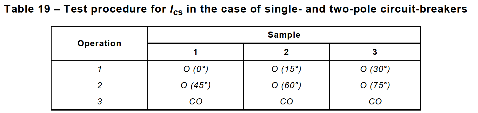
b)For single-pole and two-pole circuit-breakers the sequence of operation is:
O – t – O – t – CO
For the O operations, the auxiliary switch A is synchronized with respect to the voltage wave so that the circuit is closed on the point 0° on the wave for the O operation on the first sample.
This point is then shifted by 45° for the second O operation on the first sample; for the second sample, the two O operations shall be synchronized at 15° and 60° and for the third sample at 30° and 75°.
The synchronization tolerance shall be ±5°.
For two-pole circuit-breakers, the same pole shall be used as reference for the purpose of synchronization.
This test procedure is shown in table 19.
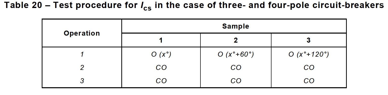
c) For three-pole and four-pole circuit-breakers the sequence of operations is:
O – t – CO – t – CO
For the O operations, the auxiliary switch A is synchronized with respect to the voltage wave so that the circuit is closed on any point (x°) on the wave for the O operation on the first sample.
This point is then shifted by 60° for the O operation on the second sample and by a further 60° for the O operation on the third sample.
The synchronization tolerance shall be ±5°. The same pole shall be used as reference for the purpose of synchronization for the different samples.
This test procedure is shown in table 20.
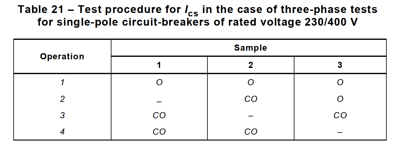
d)For single-pole circuit-breakers of rated voltage 230/400 V an additional set of three samples is tested in a circuit according to figure 5.
These samples are inserted one in each phase of the test circuit, without synchronization of the auxiliary switch A establishing the short-circuit.
No connection shall be made between the neutral of the supply and the common point on the load side of the circuit-breakers.
The test procedure is shown in table 21.
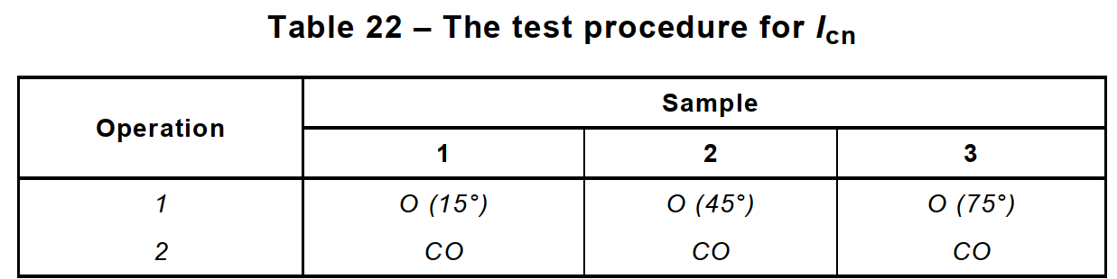
9.12.11.4.3 Test at rated short-circuit capacity (Icn)
a)The test circuit is calibrated according to 9.12.7.1 and 9.12.7.2.
Three samples are tested in the relevant circuit specified in 9.12.11.3.
When the supply and load terminals of the circuit-breakers under test are not marked, two of the samples are connected in one direction and the third sample in the reverse direction.
The sequence of operations is
O – t – CO
For the O operations, the auxiliary switch A is synchronized with respect to the voltage wave so that the circuit is closed on the point 15° on the wave for the O operation on the first sample.
This point is then shifted by 30° for the O operation of the second sample and by further 30° for the O operation of the third sample.
The synchronization tolerance shall be ±5°.
For multipole circuit-breakers the same pole shall be used as reference for the purpose of synchronization.
The test procedure is shown in table 22.
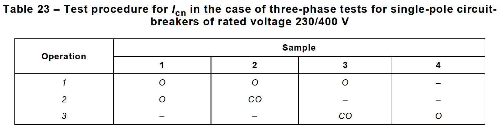
b)For single-pole circuit-breakers of rated voltage 230/400 V, an additional set of four samples is tested in a circuit according to figure 5.
Three of these samples are inserted one in each phase of the test circuit, without synchronization of the auxiliary switch A establishing the short-circuit.
No connection shall be made between the neutral of the supply and the common point on the load side of the circuit-breakers.
The test procedure is shown in table 23.
After the second O operation of the sample shown as No. 1 in table 23 this sample shall be replaced by the fourth sample.
9.12.12 Verification of the circuit-breaker after short-circuit tests
9.12.12.1 Verifications after the tests at reduced short-circuit currents, at 1 500 A and at service short-circuit capacity
After the tests according to 9.12.11.2, 9.12.11.3 or 9.12.11.4.2, the circuit-breakers shall show no damage impairing their further use and shall, without maintenance, withstand the following tests.
a)Leakage current across open contacts, according to 9.7.6.3.
b)Dielectric strength tests according to 9.7.3, carried out between 2 h and 24 h after the short-circuit tests at a voltage of 500 V less than the value prescribed in 9.7.5 and without previous humidity treatment.
During these tests, after the test carried out under the conditions specified in item a) of 9.7.2, it shall be verified that the indicating means show the open position and during the test carried out under the conditions specified in item b) of 9.7.2 the indicating means shall show the closed position.
c) Moreover, after the test of 9.12.11.3 or 9.12.11.4.2, the circuit-breakers shall not trip when a current equal to 0,85 times the conventional non-tripping current is passed through all poles for the conventional time, starting from cold.
At the end of this verification the current is steadily increased, within 5 s, to 1,1 times the conventional tripping current.
The circuit-breakers shall trip within the conventional time.
9.12.12.2 Verifications after the short-circuit test at rated short-circuit capacity
After the tests according to 9.12.11.4.3, the polyethylene foil shall show no holes visible with normal or corrected vision without additional magnification and the circuit-breakers shall show no damage impairing their further use and shall, without maintenance, withstand the following tests:
a)Leakage current across open contacts, according to 9.7.6.3.
b)Dielectric strength tests according to 9.7.3, carried out between 2 h and 24 h after the short-circuit tests at a voltage of 900 V and without previous humidity treatment.
During these tests, after the test carried out under the conditions specified in item a) of 9.7.2, it shall be verified that the indicating means show the open position, and during the test carried out under the conditions specified in item b) of 9.7.2 the indicating means shall show the closed position.
c) Moreover the circuit-breakers shall trip within the time corresponding to the test c of table 7 when a current equal to 2,8 In is passed through all poles, the lower time limit being 0,1 s instead of 1 s.
The sample shown as number 1 in table 23 is not subjected to the verification of this subclause, but it shall nevertheless comply with the requirements of 9.12.10.
9.13 Mechanical stresses
9.13.1 Mechanical shock
9.13.1.1 Test device
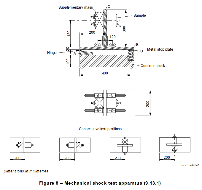
The circuit-breaker is subjected to mechanical shocks using an apparatus as shown in figure 8.
A wooden base A is fixed to a concrete block and a wooden platform B is hinged to base A. This platform carries a wooden board C, which can be fixed at various distances from the hinge and in two vertical positions.
The end of board B bears a metal stop-plate D which rests on a coiled spring having a constant c of 25 N/mm.
The circuit-breaker is secured to the vertical board in such a way that the distance of the horizontal axis of the sample is 180 mm from the platform, the vertical board being in turn so fixed that the distance of the mounting surface is 200 mm from the hinge, as shown in the figure 8.
On the surface C, opposite the mounting surface of the circuit-breaker, a supplementary mass is fixed so that the static force on the metal stop-plate is 25 N in order to ensure that the moment of inertia of the complete system is substantially constant.
9.13.1.2 Test procedure
With the circuit-breaker in the closed position, but not connected to any electrical source, the platform is lifted at its free end and then allowed to fall 50 times from a height of 40 mm, the interval between consecutive falls being such that the sample is allowed to come to rest.
The circuit-breaker is then secured to the opposite side of the vertical board C and the platform is allowed to fall 50 times as before.
After this test, the vertical board is turned through 90° about its vertical axis and, if necessary, repositioned so that the vertical axis of symmetry of the circuit-breaker is 200 mm from the hinge.
The platform is then allowed to fall 50 times as before, with the circuit-breaker on one side of the vertical board, and 50 times with the circuit-breaker on the opposite side.
Before each change of position, the circuit-breaker is manually opened and closed.
During the tests, the circuit-breaker shall not open.
9.13.2 Resistance to mechanical stresses and impact
Compliance is checked on those exposed parts of the circuit-breaker mounted as for normal use (see note to 8.1.6), which may be subjected to mechanical impact in normal use, by the test of 9.13.2.1 for all types of circuit-breakers and, in addition, by the tests specified in:
– 9.13.2.2 for screw-in type circuit-breakers;
– 9.13.2.3 for circuit-breakers intended to be mounted on a rail and for all types of plug-in circuit-breakers designed for surface mounting;
– 9.13.2.4 for plug-in type circuit-breakers, the holding in position of which depends solely on their connections.
Circuit-breakers only intended to be totally enclosed are not submitted to this test.
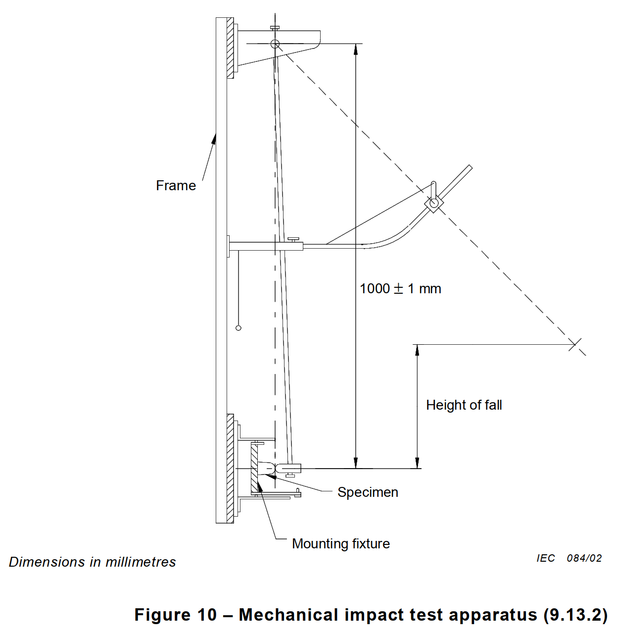
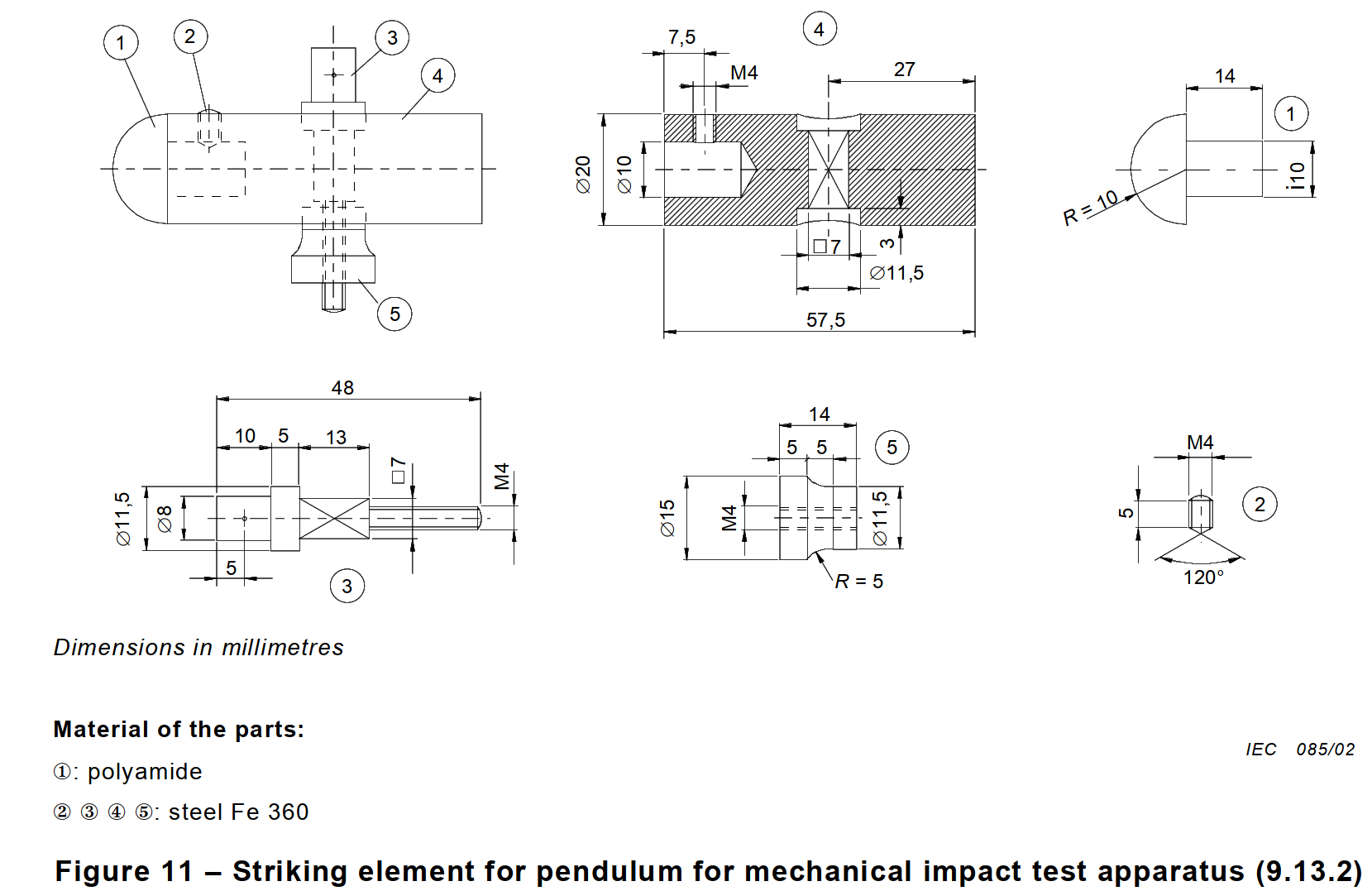
9.13.2.1 The samples are subjected to blows by means of an impact-test apparatus as shown in figures 10 to 14.
The head of the striking element has a hemispherical face of radius 10 mm and is of polyamide having a Rockwell hardness of HR 100.
The striking element has a mass of (150 ± 1) g and is rigidly fixed to the lower end of a steel tube with an external diameter of 9 mm and a wall thickness of 0,5 mm, which is pivoted at its upper end in such a way that it swings only in a vertical plane.
The axis of the pivot is (1 000 ± 1) mm above the axis of the striking element.
For determining the Rockwell hardness of the polyamide of the head of the striking element, the following conditions apply:

The design of the test apparatus is such that a force of between 1,9 N and 2,0 N has to be applied to the face of the striking element to maintain the tube in the horizontal position.
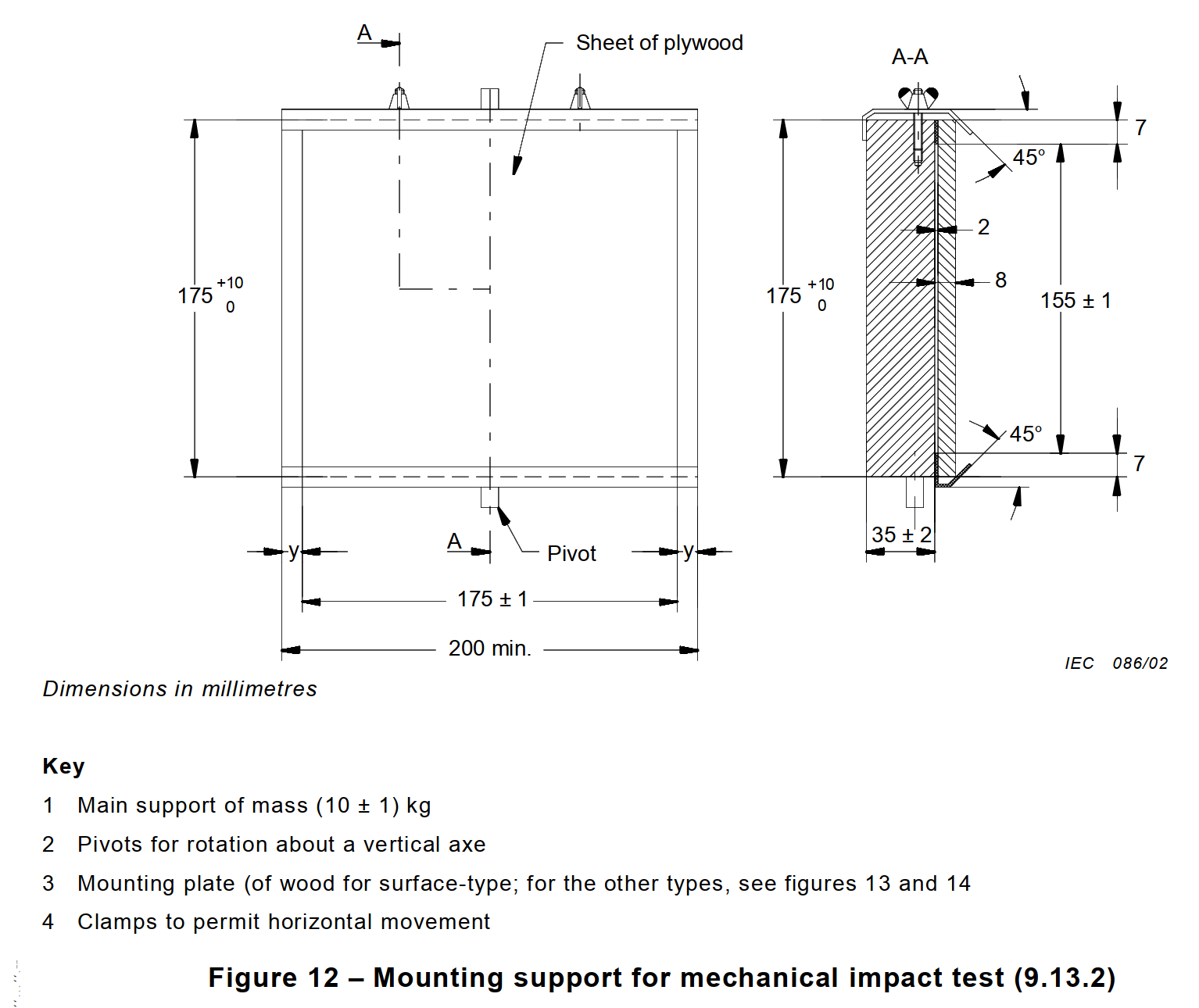
Surface-type circuit-breakers are mounted on a sheet of plywood, 8 mm thick and 175 mm square, secured at its top and bottom edges to a rigid bracket, which is part of the mounting support, as shown in figure 12.
The mounting support shall have a mass of (10 ± 1) kg and shall be mounted on a rigid frame by means of pivots.
The frame is fixed to a solid wall.
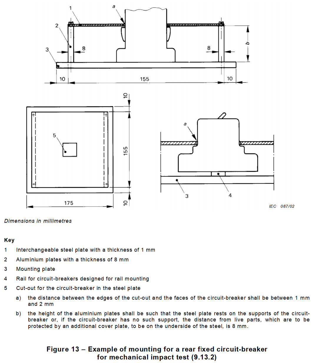
Flush-type circuit-breakers are mounted in a device as shown in figure 13, which in turn is fixed to the mounting support shown in figure 12.
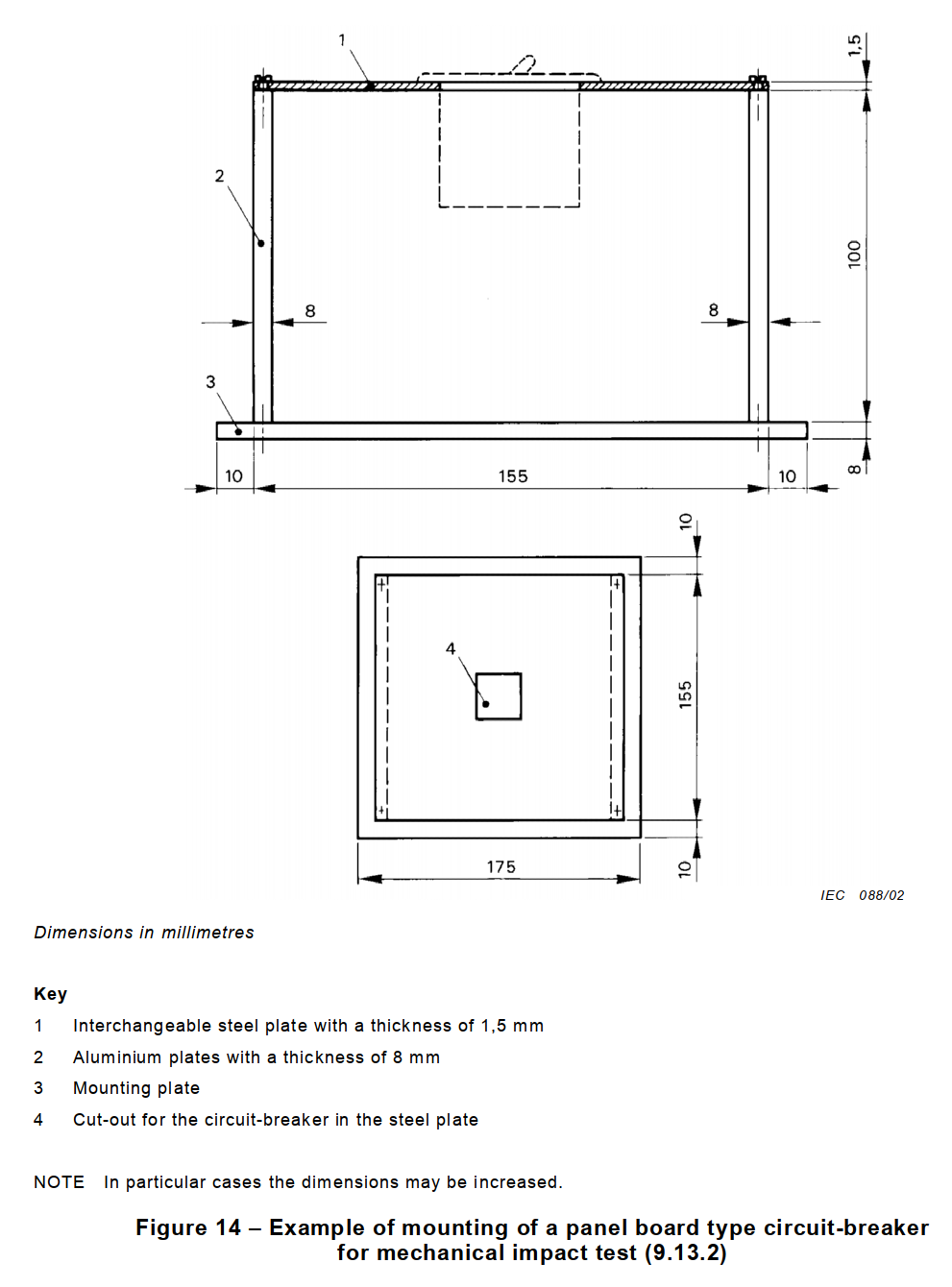
Panel board type circuit-breakers are mounted in a device as shown in figure 14, which in turn is fixed to the mounting support shown in figure 12.
Plug-in type circuit-breakers are mounted complete with the appropriate means for the plug-in connection, which means are fixed on the sheet of plywood for the surface-type, or in the device according to figure 13 for the flush-type or figure 14 for the panel-board-type, as applicable.
Screw-in type circuit-breakers are mounted in their appropriate base which is fixed to a mounting plate made of a plywood sheet, 8 mm thick and 175 mm square.
Circuit-breakers for screw fixing are fixed by means of screws.
Circuit-breakers for rail mounting are mounted on their appropriate rail.
Circuit-breakers intended both for screw fixing and for rail mounting shall be fixed with screws for the tests.
The design of the test apparatus is such that
– the sample can be moved horizontally and turned about an axis perpendicular to the
surface of the plywood;
– the plywood can be turned about a vertical axis.
The circuit-breaker is mounted on the plywood or on the appropriate device as for normal use, with covers, if any, so that the point of impact lies in the vertical plane through the axis of the pivot of the pendulum.
Cable entries which are not provided with knock-outs are left open. If they are provided with knock-outs, two of them are opened.
Before applying the blows, fixing screws of bases, covers and the like are tightened with a torque equal to two-thirds of that specified in table 10.
The striking element is allowed to fall from a height of 10 cm onto surfaces which are exposed when the circuit-breaker is mounted as for normal use.
The height of fall is the vertical distance between the position of a checking point when the pendulum is released and the position of that point at the moment of impact.
The checking point is marked on the surface of the striking element where the line through the point of intersection of the axis of the steel tube of the pendulum and that of the striking element, and perpendicular to the plane through both axes, meets the surface.
NOTE 2 Theoretically, the centre of gravity of the striking element should be the checking point. As the centre of gravity is difficult to determine, the checking point is chosen as specified above.
Each circuit-breaker is subjected to ten blows, two of them being applied to the operating means and the remainder being evenly distributed over the parts of the sample likely to be subjected to impacts.
The blows are not applied to knock-out areas or to any openings covered by transparent material. In general, one blow is applied on each lateral side of the sample after it has been turned as
far as possible, but not through more than 60°, about a vertical axis, and two blows are applied, each approximately midway between the blows on a lateral side and the blows on the operating means.
The remaining blows are then applied in the same way, after the sample has been turned through 90° about that of its axes which is perpendicular to the plywood.
If cable entries or knock-outs are provided, the sample is so mounted that the two lines of blows are as nearly as possible equidistant from these entries.
Two blows shall be applied on the operating means as follows: one when the operating means is in the closed position and the other when it is in the open position.
After the test the samples shall show no damage within the meaning of this standard. In particular covers which, when broken, make live parts accessible or impair the further use of the circuit-breaker, operating means, linings and barriers of insulating material and the like, shall not show such damage.
In case of doubt, it shall be verified that removal and replacement of external parts, such as enclosures and covers, is possible without these parts or their lining being damaged.
NOTE 3 Damage to the appearance, small dents which do not reduce the creepage distances or clearances below the values specified in 8.1.3 and small chips which do not adversely affect the protection against electric shock are neglected.
9.13.2.2 Screw-in type circuit-breakers are screwed home in an appropriate base, a torque of 2,5 Nm being applied for 1 min.
After the test the sample shall show no damage impairing its further use.
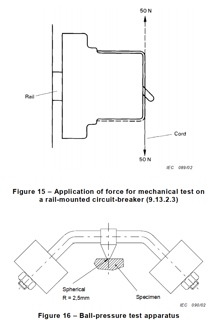
9.13.2.3 Circuit-breakers designed to be mounted on a rail are mounted as for normal use, but without cables being connected and without any cover or coverplate, on a rail rigidly fixed on a vertical rigid wall.
Plug-in circuit-breakers designed for surface mounting are mounted complete with the appropriate means for the plug-in connection but without cables being connected and without any cover-plate.
A downward vertical force of 50 N is applied without jerks for 1 min on the forward surface of the circuit-breaker, immediately followed by an upward vertical force of 50 N for 1 min (see figure 15).
During this test, the circuit-breaker shall not become loose and after the test the circuit-breaker shall show no damage impairing its further use.
9.13.2.4 Plug-in type circuit-breakers, the holding in position of which depends solely on their connections, are mounted, complete with the appropriate plug-in base but without cables being connected and without any cover-plate, on a vertical rigid wall.
A force of 20 N is applied to the circuit-breaker portion at a point equidistant between the plug-in connections, without jerks for 1 min (see figure 17).
During this test the circuit-breaker portion shall not become loose and shall not move from the base portion and after the test both portions shall show no damage impairing their further use.
9.14 Test of resistance to heat
9.14.1 The samples, without removable covers, if any, are kept for 1 h in a heating cabinet at a temperature of (100 ± 2) °C; removable covers, if any, are kept for 1 h in the heating cabinet at a temperature of (70 ± 2) °C.
During the test the samples shall not undergo any change impairing their further use and sealing compound, if any, shall not flow to such an extent that live parts are exposed.
After the test and after the samples have been allowed to cool down to approximately room temperature, there shall be no access to live parts which are normally not accessible when the samples are mounted as for normal use, even if the standard test finger is applied with a force not exceeding 5 N.
After the test, markings shall still be legible.
Discoloration, blisters or a slight displacement of the sealing compound are disregarded, provided that safety is not impaired within the meaning of this standard.
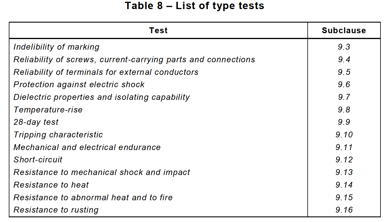
9.14.2 External circuit-breaker parts made of insulating material necessary to retain in position current-carrying parts and parts of the protective circuit are subjected to a ball-pressure test by means of the apparatus shown in figure 16 except that, where applicable, the insulating parts necessary to retain in position the terminals for protective conductors in a box shall be tested as specified in 9.14.3.
The part to be tested is placed on a steel support with the appropriate surface in the horizontal position and a steel ball of 5 mm diameter is pressed against this surface with a force of 20 N.
The test is made in a heating cabinet at a temperature of (125 ± 2) °C.
After 1 h, the ball is removed from the sample which is then cooled down within 10 s to approximately room temperature by immersion in cold water.
The diameter of the impression caused by the ball is measured and shall not exceed 2 mm.
9.14.3 External circuit-breaker parts made of insulating material not necessary to retain in position current-carrying parts and parts of the protective circuit, even though they are in contact with them, are subjected to a ball-pressure test in accordance with 9.14.2, but the test is made at a temperature of (70 ± 2) °C, or (40 ± 2) °C plus the highest temperature rise, determined for the relevant part during the test of 9.8, whichever is the higher.
NOTE 1 For the purpose of the tests of 9.14.2 and 9.14.3, bases of surface-type circuit-breakers are considered as external parts.
NOTE 2 The tests of 9.14.2 and 9.14.3 are not made on parts of ceramic material.
NOTE 3 If two or more of the insulating parts referred to in 9.14.2 and 9.14.3 are made of the same material, the test according to 9.14.2 or 9.14.3, as applicable, is carried out on only one of these parts.
9.15 Resistance to abnormal heat and to fire (glow-wire test)
The glow-wire test is performed in accordance with Clauses 4 to 10 of IEC 60695-2-10 under the following conditions:
– for external parts of circuit-breakers made of insulating material necessary to retain in position current-carrying parts and parts of the protective circuit, by the test made at a temperature of (960 ± 15) °C;
– for all other external parts made of insulating material, by the test made at a temperature of (650 ± 10) °C.
NOTE 1 The glow-wire test is applied to ensure that an electrically heated test wire under defined test conditions does not cause ignition of insulating parts, or to ensure that a part of insulating material, which might be ignited by the heated test wire under defined conditions, has a limited time to burn without spreading fire by flame or burning parts or droplets falling down from the tested part.
NOTE 2 For the purpose of this test, bases of surface-type circuit-breakers are considered as external parts. NOTE 3 The test is not made on parts of ceramic material.
NOTE 4 If a number of insulating parts is made of the same material, the test is carried out only on one of these parts, according to the appropriate glow-wire test temperature.
The test is made on one sample.
In case of doubt, the test is repeated on two further samples.
The test is made by applying the glow-wire once.
The sample shall be positioned during the test in the most unfavourable position of its intended use (with the surface tested in a vertical position).
The tip of the glow-wire shall be applied to the specified surface of the test sample taking into account the conditions of intended use under which a heated or glowing element may come into contact with the sample.
The sample is regarded as having passed the glow-wire test if
– there is no visible flame and no sustained glowing,
– flames and glowing on the sample extinguish themselves within 30 s after the removal of the glow-wire.
There shall be no ignition of the tissue paper or scorching of the pinewood board.
9.16 Test of resistance to rusting
All grease is removed from the parts to be tested by immersion in a cold chemical degreaser such as methyl-chloroform or refined petrol, for 10 min. The parts are then immersed for 10 min in a 10 % solution of ammonium chloride in water at a temperature of (20 ± 5) °C.
Without drying, but after shaking off any drops, the parts are placed for 10 min in a box containing air saturated with moisture at a temperature of (20 ± 5) °C.
After the parts have been dried for 10 min in a heating cabinet at a temperature of (100 ± 5) °C, their surfaces shall show no signs of rust.
NOTE 1 Traces of rust on sharp edges and any yellowish film removable by rubbing are ignored.
For small springs and the like and for inaccessible parts exposed to abrasion, a layer of grease may provide sufficient protection against rusting. Such parts are only subjected to the test if there is a doubt as to the effectiveness of the grease film, and in such a case the test is made without previous removal of the grease.
NOTE 2 When using the liquid specified for the test, adequate precautions should be taken to prevent inhalation of the vapour.