
8. Measurement of Test Specimens
8.1 Measure dimensions up to and including 25 mm (1 in.) using a dial-type gauge with a minimum foot area of 650 mm2(1 in.2). Pressure on the foot shall be held to 190 +- 50 Pa (0.028 +- 0.007 psi).
NOTE 2—Where foam is appreciably compressed by this test method, foot area and loading shall be as agreed upon between the purchaser and the supplier.
NOTE 3—Thickness of materials having irregular surface characteristics shall be measured as agreed upon between the purchaser and the supplier.
8.2 Dimensions over 25 mm (1 in.) may be measured with a dial gauge, scale, or tape. Take care not to distort the test specimen.
8.3 The scale, tape, or gauge shall be graduated to permit measurements within +-1 % of the dimension to be measured.
8.4 Results reported shall be the average of a minimum of three equally spaced measurements of length and width and for thickness shall be the average of the center and four equally spaced measurements around the perimeter of the specimens.
Suffix Tests
Suffix B—Compression Set Under Constant Deflection
10. Scope
10.1 This test method covers the deflection of the foam specimen under a compressive force and under specified conditions of time and temperature, then noting the effect on the thickness of the specimen after releasing the compressive force.
11. Apparatus
11.1 Compression Device, consisting of two or more flat plates arranged so the plates are held parallel to each other by bolts or clamps, and the space between the plates is adjustable to the required deflection thickness by means of spacers.
12. Test Specimens
12.1 The test specimens shall have parallel top and bottom surfaces and essentially perpendicular sides.
12.2 Specimens shall be 50 by 50 by 25 mm (2 by 2 by 1 in.) unless otherwise specified. Specimens less than 25 mm in thickness shall be plied up, without the use of an adhesive, to produce a total thickness of 25 mm.
NOTE 5—To obtain accurate data when testing foams with large cells or irregular surfaces, or both, larger samples approximately 100 by 100 by 25 mm (4 by 4 by 1 in.) are recommended.
13. Number of Specimens
13.1 Test three specimens for each sample. The values reported shall be the mean of those observed. If any value deviates more than 20 % from this mean, test two additional specimens and report the mean for all five values.
14. Procedure
14.1 Perform the entire test procedure at 23 +- 2°C (73.4 +-3.6°F).
NOTE 6—See Practice D 1349 if conditions other than these are desired.
14.2 Measure the test specimen original thickness (to) in accordance with the procedure in Section 8.
14.3 Place the test specimen in the apparatus and compressively deflect it to 50 % +- 1 % of its thickness.
14.4 Allow the test specimen to remain deflected in the apparatus for 22 h +- 30 minutes.
14.5 Remove the specimen from the test apparatus at the end of the 22-h period. Measure the final thickness ( tf) after 24h +- 30 minutes of recovery.
15. Calculation
15.1 Calculate the constant deflection compression set, expressed as a percentage of the original thickness, as follows:

where:
Cd= compression set expressed as a percent of the original thickness,
to= original thickness, mm (in.), and
tf= thickness of the specimen after the specified recovery period, mm. (in.)
16. Report
16.1 Report the average compression set value, of the three specimens tested, for each sample, except as noted in 14.1.
Suffix D—Compression Deflection (Also called Load Deflection or Compressive Strength)
18. Scope
18.1 This test method covers the measurement of the force necessary to produce a 25 % compression over the entire top area of the foam specimen.
NOTE 7—Compression deflection tests other than at 25 % may be specified as agreed upon between the purchaser and the supplier.
19. Apparatus
19.1 An apparatus shall be provided having a flat compression foot, larger than the specimen to be tested, connected to a force-measuring device and mounted in a manner such that the product or specimen can be deflected (compressed) at a speed of 0.2 to 4 mm/s (0.5 to 2 in./min). The apparatus shall be arranged to support the specimen on a level horizontal plate.
20. Test Specimens
20.1 The test specimen shall be 50 by 50 by 25 mm (2 by 2 by 1 in.) with parallel top and bottom surfaces. The thickness shall be no greater than 75 % of the minimum top dimension.
20.2 Specimens shall be a minimum of 2500 mm2(4 in.2)in area and have a minimum thickness of 25 mm (1 in.).
Specimens less than 25 mm thick shall be plied up, without the use of cement, to a minimum of 25 mm.
NOTE 8—Specimens less than 25 mm (1 in.) thick may be tested without being plied up, but the thickness must be specified.
21. Number of Specimens
21.1 Test three specimens for each sample. The values reported shall be the mean of those observed. If any value deviates more than 20 % from this mean, test two additional specimens and report the mean for all five values.
22. Procedure
22.1 Place the specimen centered in the line of the axial load on the supporting plate of the apparatus.
22.2 Bring the compression foot into contact with the specimen and determine the thickness after applying a total pretest-pressure of 190 +- 50 Pa (0.028 +- 0.007 psi) to the specimen area. Compress the specimen 25 +- 0.5 % of this thickness at 12.5 mm/min (0.5 in./min) and take the reading of the load immediately, unless another speed is specified.
NOTE 9—Where foam is appreciably compressed by this pretest-pressure, foot area and loading shall be as agreed upon between the purchaser and the supplier.
23. Calculation
23.1 Calculate the 25 % compression deflection force, per unit area of specimen, expressed as kilopascals (or pounds-force per square inch), as follows:

where:
CD = compression deflection force per unit of specimen area, kPa (psi),
F= force required to compress the specimen 25 % of the thickness as measured in 8.2, N (lbf), and
A= specimen compression contact surface area, m2(in.2).
24. Report
24.1 Report the average thickness after pretest pressure and the average compression deflection, for the three specimens tested, in kilopascals (or pounds-force per square inch), required for 25 % compression, except as noted in 22.1.
26. Test Method D 624
26.1 Die C shall be used.
26.2 Test the material at the thickness to be supplied, unless otherwise arranged by agreement between the purchaser and the supplier.
Suffix L—Water Absorption
27. Scope
27.1 This test method covers the measurement of the water absorbed by olefin polymer flexible cellular materials during submersion under pressure.
28. Test Specimens
28.1 Test specimens shall be 100 by 100 mm (4 by 4 in.) by the thickness of material being supplied. The specimen may or may not have natural skins on top, bottom, or both surfaces.
29. Number of Specimens
29.1 Test three specimens for each sample. The values reported shall be the mean of those observed. If any value deviates more than 20 % from this mean, test two additional specimens and report the mean for all five values.
30. Procedure
30.1 Measure the area of the cut surfaces in accordance with Section 8 and calculate the area of the cut surfaces.
30.2 Weigh the specimens and submerge under a 3-m (10-ft) head of water (equal to 30 kPa or 4.35 psi) at room temperature (18 to 29°C (65 to 90°F)) for 48 h. Then place the specimens in a stream of air for the minimum time required to remove visible water from the surfaces and reweigh.
NOTE 10—To remove visible and entrapped water from the surface and cut edges, direct a stream of air (using approximately 30 psi air pressure) at the surfaces and cut edges at approximately a 45 degree angle and from the distance of approximately 6 mm (0.25 in.) from the surface for approximately 4 min.
31. Calculation
31.1 Calculate the water absorption, expressed in kg/m2(lb/ft2) of cut surfaces (surfaces without skin or rind) as follows:
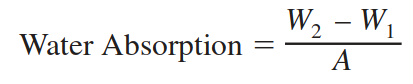
where:
W1= specimen mass before immersion, kg (lb),
W2= specimen mass after immersion, kg (lb), and
A= area of cut surface, m2(ft2).
32. Report
32.1 Report the average water absorption in kg/m 2(lb/ft2) of the three specimens tested, except as noted in 30.1.
Suffix M—Flammability Ease of Ignition
34. See Test Method D 2863
Suffix R2—Energy Absorption
35. See Test Method F 355
35.1 Procedure A of Test Method F 355 shall be used.
35.2 The impact velocity shall be 3.45 +- 0.17 m/s.
NOTE 11—Approximate drop height is 60 cm (24 in.).
35.3 Conduct the test at 23 +- 2°C (73.4 +- 3.6°F).
35.4 The test specimens shall be 25 mm (1 in.) thick.
Suffix S—Thermal Stability
36. Scope
36.1 This test method covers the determination of dimensional stability of foam in any direction, at elevated temperature.
37. Apparatus
37.1 Oven, circulating-air, capable of holding the set temperature to a tolerance of +-1%.
38. Test Specimen
38.1 The test specimens shall be 250 by 250 by 25 mm (10 by 10 by 1 in.). Where finished goods with smaller than the specified test specimen are to be tested, the full available dimensions shall be used.
NOTE 12—An alternative test method is to cut 305 by 305-mm (12 by 12-in.) specimens and mark off the 250 by 250-mm (10 by 10-in.) dimensions.
39. Number of Specimens
39.1 A single specimen shall be tested for each sample.
40. Procedure
40.1 Determine all three dimensions in accordance with the procedure in Section 8.
40.2 Adjust the oven temperature to 70 +- 2°C (158 +- 3°F).
40.3 Expose the test specimen in the oven at the above temperature for 24 h.
40.4 Remove the test specimen and allow to cool at 23+- 2°C (73.4 +- 3.6°F) for 2 h.
40.5 Determine all three dimensions at the end of the cooling period.
41. Calculation
41.1 Calculate the dimensional change for each dimension as a percent of original as follows:
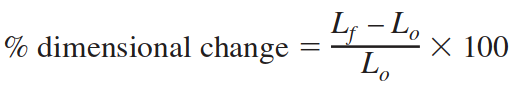
where:
Lo= original dimension, mm (in.), and
Lf= dimension at end of test, mm (in.).
42. Report
42.1 Report the dimensional change of each direction of interest as a percent of the original dimension.
42.2 Report shrinkage as negative values and growth as positive values.
Suffix T—Tensile Strength and Elongation
44. See Test Methods D 412
44.1 The samples shall be cut using the Die A, as described in Test Methods D 412.
44.2 Test the material in the thickness to be supplied, unless otherwise agreed upon between the purchaser and the supplier.
Suffix V—Thermal Conductivity
45. Test Method A
45.1 See Test Method C 177.
46. Test Method B
46.1 See Test Method C 518.
Suffix W—Density
47. Test Method A
47.1 Scope—This test method covers the determination of density of foam by calculation from the mass and volume of a regularly shaped specimen.
47.2 Test Specimen—A representative test specimen of regular shape, not less than 16 cm3(1 in.3) shall be cut from the sample to be tested.
NOTE 13—Larger specimens may be necessary when testing coarse cell foams.
47.3 Number of Specimens—A single specimen shall be tested for each sample.
47.4 Procedure:
47.4.1 Weigh the specimen on a balance or scale graduated so as to permit weighing within +-1 % of the mass to be measured.
47.4.2 Determine the dimensions of the specimen in accordance with Section 8.
47.5 Calculation—Calculate the density as follows:
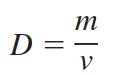
where:
D = density, kg/m3(lb/ft3),
m = mass, kg (lb), and
v = volume, m 3(ft3).
47.6 Report—Report density to the nearest 1.0 kg/m3(0.1lb/ft3).
49. Test Method B
49.1 Scope—This test method covers the determination of the density of closed-cell foams where the volume is determined by a liquid displacement method and mass.
NOTE 14—This test method is particularly appropriate when testing small or irregularly shaped samples.
49.2 Apparatus:
49.2.1 Scale or Balance.
49.2.2 Immersion Vessel, as shown in Fig. 1.
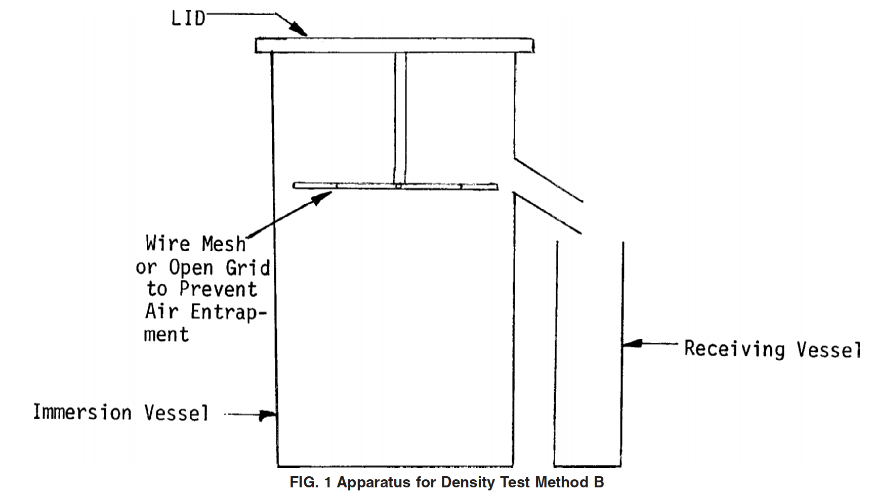
49.2.3 Receiving Vessel, as shown in Fig. 1.
49.3 Test Specimen—Cut a representative test specimen not less than 16 cm3(1 in.3) from the sample to be tested.
NOTE 15—Larger specimens may be necessary when testing coarse cell foams or foams with irregular surfaces.
49.4 Number of Specimens—Test a single specimen for each sample.
49.5 Procedure:
49.5.1 Weigh the specimen on a balance or scale graduated so as to permit weighing within +-1 % of the mass to be measured.
49.5.2 Fill the immersion vessel with liquid until it overflows. Insert the lid in the vessel.
49.5.3 Determine the tare mass of the receiving vessel and, when the flow rate has decreased to less than two drops per minute, place under the overflow spout of the immersion vessel.
49.5.4 Remove the lid, place the test specimen in the immersion vessel, and replace the lid.
49.5.5 When the flow rate has decreased to less than two drops per minute, weigh the receiving vessel.
49.6 Calculation—Calculate the density as follows:
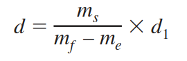
d =density, kg/m3(lb/ft3),
ms=mass of test specimen, g (lb),
mf=mass of receiving vessel and liquid, g (lb),
me=tare mass of receiving vessel, g (lb), and
d1=density of liquid, kg/m3(lb/ft3).
49.7 Report—Report density to the nearest 1.0 kg/m3(0.1 lb/ft3).
Suffix AA—Buoyancy (Also called Specific Buoyancy)
51. Scope
51.1 This buoyancy test is applicable to closed-cell materials for determining the buoyancy of the foam in fresh water at a standard temperature of 20°C (68°F).
52. Apparatus
52.1 Scale, Tape, or Gauge, as outlined in Section 8, for determining the density using Test Method A or balance and container as outlined in Section 49 for determining the density using Test Method B.
52.2 Rigid Tank, containing fresh water at 20 +- 3°C (68 +-5.4°F) in which specimens are submerged.
52.3 Basket(s), wire or mesh weighted, to hold specimens in submerged position.
52.4 Scales, mounted over the water tank to weigh the basket and specimens while submerged.
53. Test Specimens
53.1 The test specimens shall be 300 by 300 mm (12 by 12 in.) by the thickness of buoyant material furnished.
NOTE 16—It is not advisable to ply up layers because this could cause entrapment of air between the layers giving erroneous results.
54. Number of Specimens
54.1 Test three specimens for each sample. The values reported shall be the mean of those observed. If any value deviates more than 20 % from this mean, test two additional specimens and report the mean for all five values.
55. Procedure
55.1 Determine the volume of each specimen using the procedure described in Section 47 or 49.
55.2 Maintain the water temperature at 20 +- 3°C (68 +-5.4°F) throughout the test.
55.3 Weigh the inverted, empty basket, including all weights necessary to hold the specimen under water, while submerged to a depth of 50 mm (2 in.).
55.4 Place the specimen under the inverted basket and submerged so the upper surface of the specimen is 50+- 6 mm (2 +- 0.25 in.) below the surface of the water.
55.5 Submerge the specimen for 24 h and reweigh the submerged basket and specimen without removing them from the water.
55.6 Calculate the fresh water buoyancy as follows:
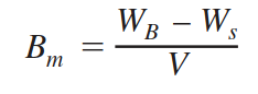
where:
Bm=measured fresh water buoyancy, kg/m3(lb/ft3),
WB=mass of submerged basket, kg (lb),
Ws=mass of submerged basket and specimen after 24 h, kg (lb), and
V= volume of specimen, m3(ft3).
56. Report
56.1 Report the average fresh water buoyancy of the three specimens tested, except as noted in 54.1.
Suffix BB—Constant Compression Creep
58. Scope
58.1 This test method covers the determination of creep properties of flexible polyolefin foam materials in the form of sheets, boards, or blocks, when subjected to a constant compressive force.
59. Summary of Test Method
59.1 A loaded, movable platen is placed on a test specimen to stimulate static constant compressive loading. By measuring the change in thickness with time, creep properties of the foam material can be obtained.
59.2 The data may be affected by specimen area, thickness, varying ambient conditions of temperature, humidity, vibration, and impact.
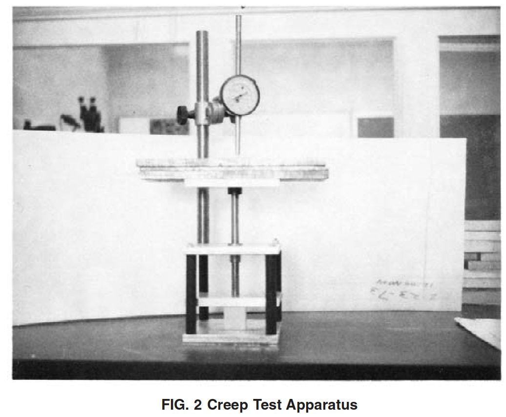
60. Apparatus
60.1 The apparatus shall consist of a rigid base plate and a force movable platen. Provisions shall be made for applying a force to the movable platen. The base plate and movable platen shall have minimum dimensions of 180 by 180 mm (4.5 by 4.5 in.). The force shall be applied to the movable platen at a pivot point located at the geometric center of the platen. A dial micrometer shall be attached to the base plate or frame of the apparatus to permit continuous measurements of the travel of the movable platen. Any force-inducing mechanism that does not interfere with measurement of the movement of the movable platen is acceptable. A suitable apparatus is shown in Fig. 2.
61. Test Specimen
61.1 Test specimens shall be right square prisms or right cylinders with minimum area of 25 cm2(4 in.2) and the maximum dimension shall be no greater than the size of the platen in 60.1. The thickness shall not exceed half of the lateral dimensions.
62. Number of Specimens
62.1 Test four specimens for each sample. The values reported shall be the mean of these observed. If any value deviates more than 20 % from this mean, test two additional specimens and report the mean of these six values.
63. Procedure
63.1 Measure the thickness of the specimen in accordance with Section 8. Record this value as the original thickness (T).
63.2 Measure the length and width of the specimen in accordance with Section 8 and record.
63.3 Assemble the apparatus described in Section 53. With the removable platen in contact with the base plate, position the dial micrometer to read thickness at the geometric center of the platen and adjust the micrometer to read zero. Raise the movable platen and center the test specimen under the movable platen on the base plate. Using appropriate means, apply the force agreed upon between the purchaser and the supplier, to the test specimen by placing the standard masses gently on the platen. Measure the total force. Start to measure the thickness of the test specimen while under load 60 +- 5 s after the force has been applied. Record this thickness as the initial thickness under force (Ti).
63.4 Creep Determination—Measure the thickness of the compressively stressed test specimen at any desired time interval, but at least at 6 min, 1 h, 24 h, and 168 h, after application of the force. More frequent readings are recommended to establish a creep versus time curve. Record the thickness at each specified time interval as the deflection thickness (Td).
63.5 Temperature and Humidity—In order to establish data that will simulate actual conditions of experience, creep may be determined at varied temperatures and humidities. Record the temperature and humidity used.
64. Calculation
64.1 Calculate the static compressive stress in pascals (or pounds-force per square inch) for the given force as follows:
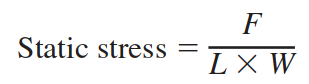
where:
F= applied force, N (or lbf),
L= length of the specimen, m (or in.), and
W= width of the specimen, m (or in.).
64.2 Calculate creep based on initial thickness under compressive force as follows:
Creep at any given time interval, %
where:
Ti= initial thickness under load, mm (in.), and
Td= deflection thickness, mm (in.).
Suffix CC—Dynamic Cushioning
66. See Test Method D 1596
66.1 A 345 +- 17 cm/s (135 +- 7 in./s) impact velocity shall be used.
NOTE 17—Approximate drop height 60 cm (24 in.).
66.2 The test shall be conducted at 23 +- 2°C (73.4 +- 3.6°F) and 50 +- 2 % relative humidity.
66.3 The test specimen shall be 50 +- 1.6 mm (2+- 0.063 in.).
66.4 The missile mass varies with the sample size and shall be such that it would be equal to 6.9 kPa (1 psi).
66.5 Record the average values for Drops 2 through 5.