AHP manufacture testing equipment for stretch-wrap films. Stretch wrap films are highly stretchable plastic films that are wrapped around certain items, as often used in the packaging industry. The main function of the film is to improve it’s loading stability for transportation, storage and contamination protection. Stretch-wrap films are commonly made of PE (LLDPE , VLDPE, PVC ….). Critical properties of stretch wrap film are elastic recovery and break strength, but also cling, puncture resistance and optical properties are very important.
Main Stretch Film Wrap Tests are as Below:
- ASTM D-5459: Elastic Recovery, Permanent deformation and Stress Retention
- ASTM D-5458: Peel Cling of Stretch Wrap Film
- ASTM D-5748: Protrusion Puncture Resistance of Stretch Wrap Film
- ASTM D-882: Tensile Properties
- ASTM D-1003: Haze
- ASTM D-1894: COF- Coefficient of Friction
- ASTM D-1922: Propagation Tear Resistance
ASTM D-5459: Elastic Recovery, Permanent deformation and Stress Retention
Apparatus
6.1 Tensile Testing Machine, with a reversible chart, complying with the requirements listed for Method A of Test Methods D882 with grips satisfactory for the purpose. Refer to section on grips in Test Methods D882.
6.2 Specimen Cutter, capable of producing nick-free 1 +- 0.001 in. (25.4 +- 0.03 mm) testing strips, with a precision of 1 +- 0.001 in. (25.4 +- 0.03 mm).4
6.3 Micrometer, capable of measuring the thickness of specimens to 0.001 in. (0.03 mm) as described in 8.9.1.1 of Specification D2103.
Specimen Preparation
8.1 Cut five strips parallel to the machine direction that are 1.0 in. (25.4 mm) wide and long enough to provide for an initial grip separation of 5 in. (127 mm).
8.2 Measure the thickness of each specimen at five equally spaced points in the area that will be between the grips to the nearest 0.001 in. (0.003 mm) and record the values.
Preparation of Apparatus
9.1 Select a load range so that the scans cover approximately two-thirds of the chart width.
9.2 Calibrate the strain gage as directed by the manufacturer of the machine. Set the rate of grip separation at 5 in./min (127 mm/min) and the initial grip separation at 5 in. (127 mm).
Conditioning
10.1 Sample Conditioning—Condition the test specimens at the standard atmospheric condition for not less than 24 h prior to testing, as described in Practice E691.
10.2 Test Conditions—Testing shall be conducted under the condition specified for specimen conditioning in 10.1.
Procedure
11.1 Clamp the first specimen in the grips so that it is free to slack but is not under tension.
11.2 Start the testing machine and chart, and elongate the specimen at 5 in./min (127 mm/min) to an extension of 15, 50, 100, 150 or 200 % and stop the testing machine and chart. (In Fig. 1, at extension AE, curve AB is generated.) 11.3 Wait 60 s or 24 h, during which time the specimen will relax. See Note 1. (In Fig. 1, extension BG is generated.)
NOTE 1—Slack in the specimen and misalignment of the grips are the major causes of non-linearity of the early part of the load-extension curves.
11.3.1 When testing materials of unknown response, investigate a series of times for recovery.
11.4 Return the crosshead to the original grip separation, simultaneously reversing the chart. (In Fig. 1, curve GCA is generated.)
11.5 Wait 180 s.
11.6 Re-elongate the specimen to the same extension as used originally in 11.2. (In Fig. 1, curve ADX is generated.) 11.7 Repeat the procedure described in 11.1-11.6 on the other four specimens.
Calculation (See Fig. 1)
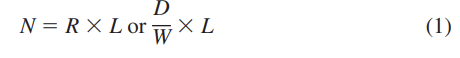
12.1 Determine the length of AD and AE in chart units. Calculate the permanent deformation in percent using Eq 1:
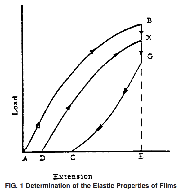

12.2 Determine the lengths of DE and AE in chart units. Calculate the elastic recovery in percent using Eq 2 (see Note 2):

NOTE 2—Percent of permanent deformation plus percent of elastic recovery = 100 %.
12.3 Determine the length of BE and GE in chart units. Calculate the stress retention in percent using Eq 3:

12.4 Read and record the force at point G in grams-force, lbs-force, or Newtons.
12.5 Calculate the average, standard deviation, and 95 % confidence limits of the average for each factor measured, including thickness, for each set of five specimens tested.
Standard Test Method for Peel Cling of Stretch Wrap Film
6 Equipment and Preparation
6.1 Apparatus—A universal testing machine with a constant rate of grip separation equipped, as follows:
6.1.1 One lightweight jaw equipped with 1 by 1.5 in. (25 by 38 mm) flat rubber-faced grips,
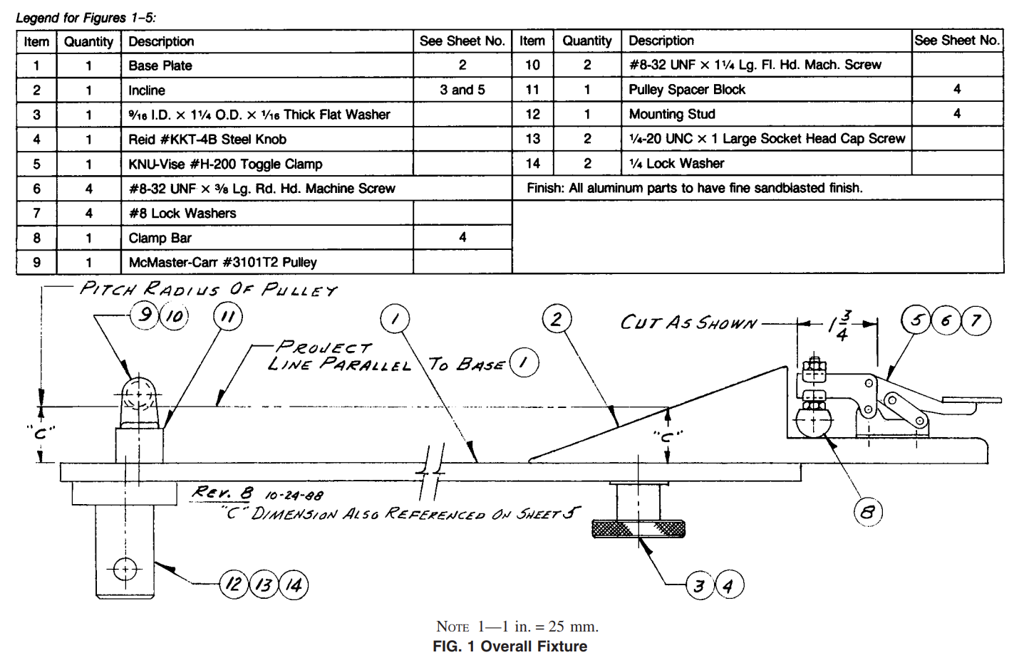
6.1.2 Cling attachment (see Figs. 1-5),
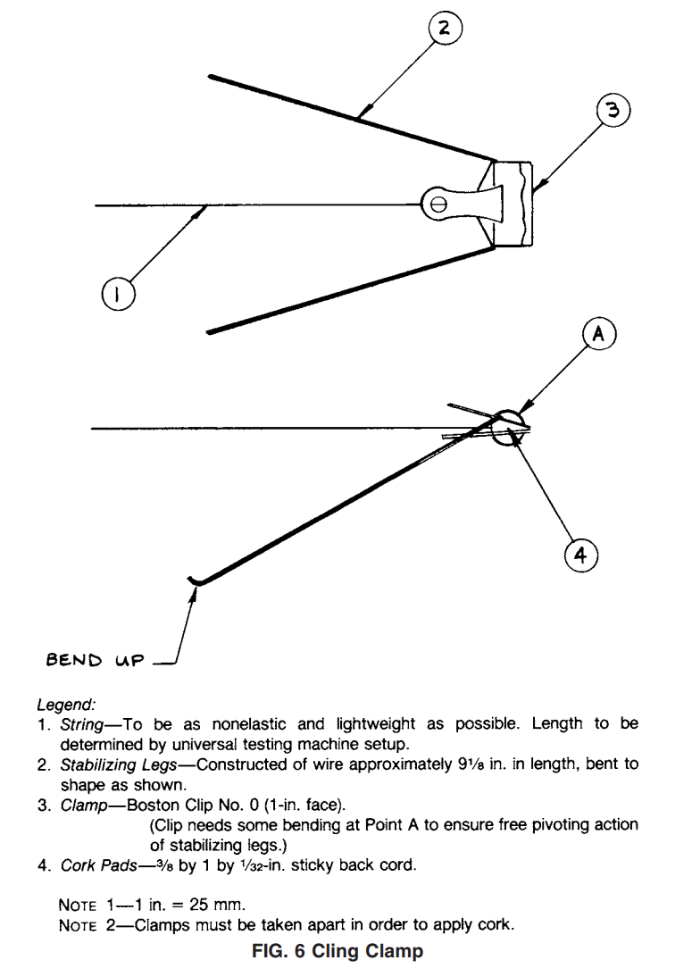
6.1.3 Cling clamp (see Fig. 6),
6.1.4 Load cell, 500-g load capacity,
6.1.5 If using pneumatic grips, air supply, 60 to 70 psi with appropriate filter,
6.1.6 Sample template, picture-frame style with inside dimensions of 5 by 20 in. (125 by 500 mm),
6.1.7 Precision sample cutter, 1 +- 0.001 in. (25.4 +- 0.03mm) width, with precision of 1 +- 0.001 in. (25.4 +- 0.03 mm),4
6.1.8 Single-edged safety razor blade,
6.1.9 Synthetic bristle paint brush, 2 in. (50 mm) wide,
6.1.10 Ruler, 12 in. (approximately 300 mm),
6.1.11 Separation paper, 8.5 by 12 in. (approximately 125 by 280 mm) bond,
6.1.12 String, 24 in. (approximately 610 mm) nonelastic, such as dental floss or fishing line,
6.1.13 Steel rod, approximately 0.25 in. (6 mm) in diameter and 10 in. (255 mm) long.
6.1.14 Cutting surface, approximately 36 by 36 in. (approximately 900 by 900 mm) plate glass, 0.25 in. (6 mm) thick.
6.2 Preparation of Apparatus:
6.2.1 Install the load cell on the upper set frame and allow 15-min warm-up period.
6.2.2 Install the upper lightweight jaw.
6.2.3 Remove the lower jaw and install the cling attachment, using the locking pin to secure.
6.2.4 Feed the end of the string not fastened to the clamp through the pulley on the cling attachment and place in the center of the upper jaw.
6.2.5 With the clamp resting at the base of the incline (which is in position on the base plate), adjust the crosshead, or the amount of string pulled through the grips, or both in combination, to achieve a distance of 5 by 7 in. (125 by 180 mm) between the top of the pulley and the bottom of the grips. Tighten the upper jaw. Adjust the crosshead return stop as necessary.
6.2.6 Set the testing machine crosshead speed for 5 in. (125 mm). (Any chart speed is acceptable.)
6.2.7 Zero, balance, and calibrate the tester in accordance with the operator’s manual.
Test Specimens
8.1 The roll to be tested must have at least three outer wraps removed just prior to sample selection.
8.2 With the film unwinding from the top of the roll, pull about 30 in. (760 mm) of sample film from the roll at a rate of approximately 8 in./s (approximately 200 mm/s). Some films are sensitive to unwind speed so a consistent rate that does not induce appearance variations, such as stripes or bars, is important.
8.3 Place the film being sampled on the glass cutting surface being cautious not to create wrinkles. Mark the machine direction (MD) of the sample. Do not touch the film test surface.
8.4 Align the paper sheets under and over the film in three locations equidistant across the film. Cut around the outside edges of the papers to form paper/film/paper sandwiches. Label the web location and side of the film that is to be on the outside of a wrapped load; this will be referred to as the “outside” surface and the other side the “inside” surface.
8.5 Using the precision sample cutter, cut a 1 in. (25.4mm) transverse direction (TD) by approximately 7 in. (180 mm) machine direction (MD) specimen from each paper/film/paper sandwich. These will be used with the corresponding 5 by 20 in. (125 by 500 mm) samples.
8.6 Using the sample template and razor blade, cut three 5 by 7 in. (125 by 180 mm) TD by MD samples corresponding to the TD locations of the 1 by 7 in. (25.4 by 180 mm) samples cut in 8.5.
8.7 Perform subsequent testing “outside” surface to “inside” surface. Conduct testing within 30 min of sample preparation. 8.8 In the case of single-side cling film, or differential cling film, it may be necessary to also test outside to outside surface or inside to inside surface.
Procedure
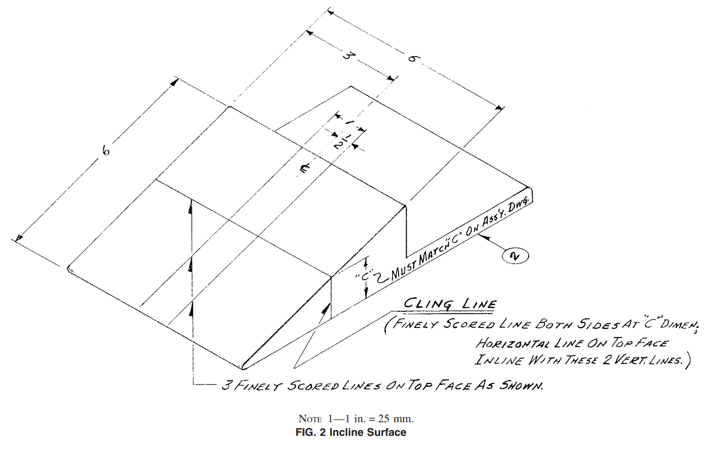
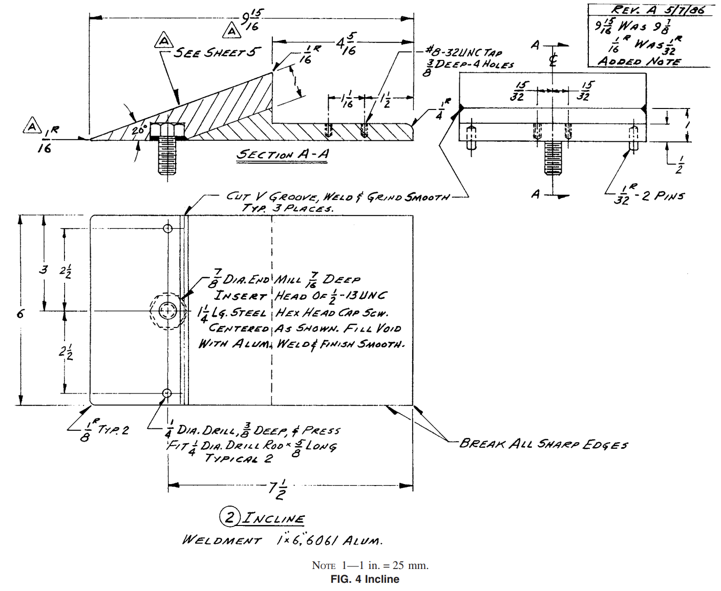
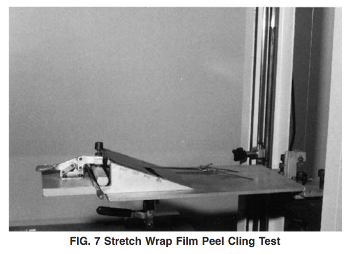
10.1 Loosen the fixture knob and push the incline up from the fixture surface. Allow the pins to hold the incline up. See Fig. 7 for a picture of test equipment and specimen set up for test.
10.2 Place a 5 by 20 in. (127 by 508 mm) sample squarely on the incline face with its outside surface up.
10.3 Tuck the film under the leading edge of the inclined bottom edge and reset the locating pins in their holes allowing the film to be clamped. Remove any obvious wrinkles and tighten the incline locking knob.
10.4 Grasp the unclamped corners of the film sample and pull back over the incline face to create a tight, smooth surface of film. A slight amount of stretching is acceptable. Do not touch the sample test area indicated by the lines on the incline face.
10.5 In accordance with the desired stretch percentage, measure down the incline face from the top and mark both edges of the film sample. The appropriate distances are as follows:
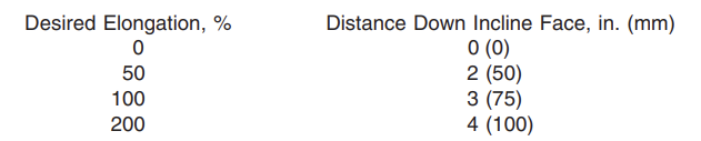
10.6 Roll the free end of the film up on the steel rod to within 1 in. (25 mm) of the marks on the film.
10.7 Elongate the sample, using the steel rod as the grip area, until the marks are aligned with the top edge of the incline.
10.8 While still holding the film tightly enough to maintain this extension, move the rod down and through the clamps and clamp the film. Some film might have to be allowed to unwind from the rod during this step to ensure proper mark positions and yet have film to clamp.
10.9 Take the corresponding 1 in. (25.4 mm) wide paper/ film/paper sandwich sample and slide the paper to expose about 0.5 in. (12.5 mm) of film.
10.10 With the “outside” surface up, place this exposed film section on the incline film sample and at the top of the incline. Align it so that the remainder of the sample, with paper still in place, will lie between the parallel guide lines that run the full face length of the incline.
10.11 With the sample positioned property, brush the exposed end down with moderate pressure. Grasp the opposite ends of the paper and gently pull the paper away from the film creating a smooth contact surface with the sample still properly aligned.
10.12 Using the wide side of the brush and moderate pressure and speed, brush the length of the 1 in. (25 mm) sample with three strokes. This will eliminate air and ensure good contact between the sample surfaces.
10.13 Roll the lower end of the 1 in. (25.4 mm) sample and insert it in the film clip.
10.14 Turn the chart and pen on and activate the crosshead. 10.15 At the moment when the 25.4-mm (1.0-in.) film specimen is separating from the incline at the horizontal cling line (see Fig. 1), mark the chart. This value is the cling force. 10.16 Turn the chart and pen off, return the crosshead, and remove the samples.
10.17 Repeat 10.1 to 10.16 for each replicate. A minimum of three replicates should be completed and the results averaged.

Standard Test Method for Protrusion Puncture Resistance of Stretch Wrap Film
Apparatus
5.1 Universal Testing Apparatus.
5.2 Integrator and Chart Recorder.
5.3 Appropriate Load Cell—The test may be performed using compression or tension load cell.
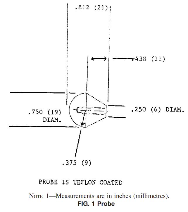
5.4 Probe—A 0.75 in. (19 mm) diameter pear-shaped TFEfluorocarbon coated probe4 (Fig. 1), for general application and standard comparison of plastic films and interlaboratory results.
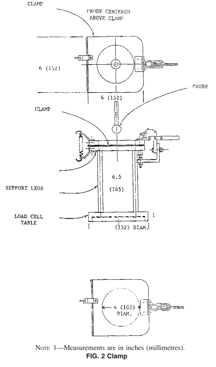
5.5 Specimen Clamping Fixture (Fig. 2).
5.6 Micrometre, conforming to Specification D2103.
5.7 Template, 6 by 6 in. (150 by 150 mm).
5.8 Specimen Cutter.
Sampling
6.1 Acceptance Sampling—Sampling shall be in accordance with Practice D1898.
6.2 Sampling for Other Purposes—The sampling and the number of test specimens depend on the purpose of the testing. Practice E122 is recommended. Test specimens are taken from several rolls of film, and where possible, from several production runs of film. Strong conclusions about a specific property of a film cannot be based on a single roll of film.
Number of Test Specimens
7.1 Test a minimum of five specimens for each sample.
Preparation of Apparatus
8.1 For specific instruction in setting up and operating the apparatus, consult the operations manual.
8.2 Install probe apparatus (Fig. 2).
8.3 Center the probe (Fig. 1) over the specimen clamping
fixture (Fig. 2).
Conditioning
9.1 Condition the test specimens at 73.4 +- 3.6°F (23 +- 2°C) and 50 6 5 % relative humidity for not less than 40 h prior to testing in accordance with Procedure A of Practice D618.
9.2 Conduct tests in the standard laboratory atmosphere of 23 +- 2°C (73.4 +- 3.6°F) and 50 +- 5 % relative humidity unless otherwise specified in the test method.
Procedure
10.1 With the probe apparatus installed, calibrate the test equipment following the manufacturer’s instructions.
10.2 Select an equipment load range so that specimen puncture occurs within 20 to 80 % of the same.
10.3 Using the template and specimen cutter, prepare a minimum of five specimens from each sample.
10.4 Measure the caliper (average of three readings) in the center of each specimen and record the average. 10.5 Set universal tester crosshead speed at 10 in./min (250 mm/min) and chart recorder speed at 10 in./min (250 mm/min). If using an integrator instead of a data acquisition system, set the counters to zero.
10.6 Clamp the specimen in the holder. Lower the probe as close as possible to the specimen without actually touching.
10.7 Set the appropriate stops and returns on the universal tester. Reset data collection devices if applicable.
10.8 Activate the universal tester. Stop the crosshead when the puncture probe passes completely through the film. Whereholes occur other than at the probe point, the specimen test results should be discarded. See Fig. 3.
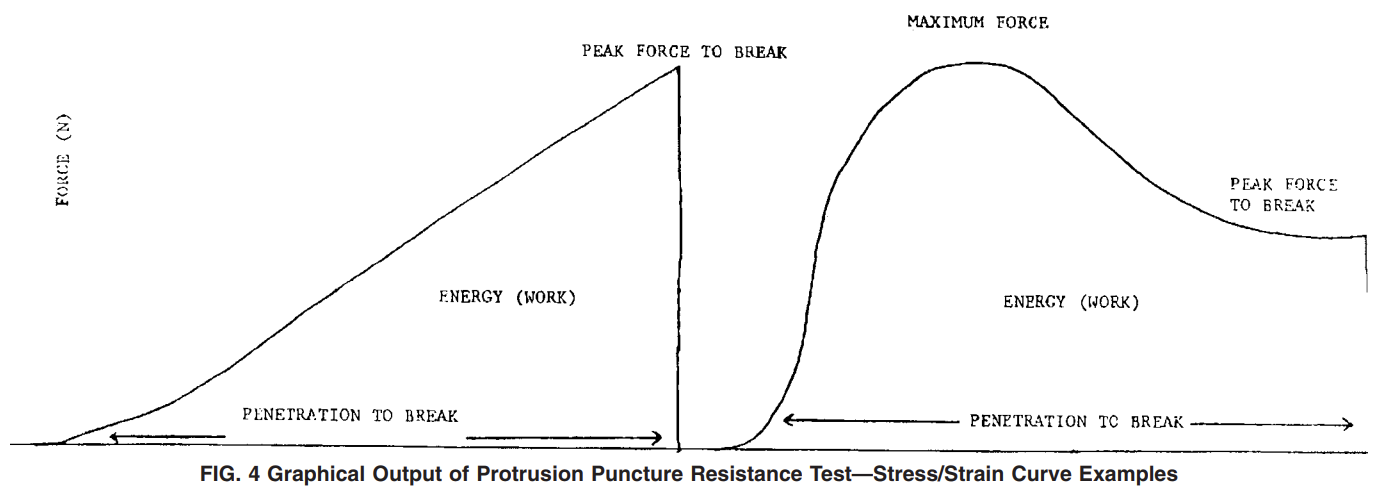
10.9 Record specimen identification, peak force at break, maximum force, energy (work) to break, and probe penetration distance at break, from mechanical testing software output.
If using chart recording instruments, record specimen identification on chart and integrator reading if used. Return crosshead to start position and remove specimen. See Fig. 4 for graphical output of test performed.
10.10 Repeat test sequence (10.1 through 10.9) for the remaining sample specimens.
Calculations
11.1 Compute the values of peak force at break, maximum force, energy (work) to break and probe penetration distance. In some instances, peak force at break and maximum force will be the same value (Fig. 4).
11.1.1 Software computed values are acceptable.
11.2 Use the following formulas for calculating the required values for data acquisition with a time based chart recorder.
11.2.1 Calculate peak force to break–peak force to achieve break, lb (N):
where:
N = peak force to break, lb (N),
R = chart reading, expressed as a decimal, %,
L = full scale load (FSL), lb, N,
D = recorded actual in. (mm) of chart in vertical axis, from start of test to finish, and
W = full scale width of chart, in. (mm).
11.2.2 Calculate the maximum force–highest force achieved during a test, lb (N):

where:
M = maximum force achieved, lb (N),
R = chart reading, expressed as a decimal, %,
L = full scale load (FSL), lb, N,
D = recorded actual in. (mm) of chart in vertical axis, from start of test to maximum force point, and W = full scale width of chart, in. (mm).
11.2.3 Calculate the probe penetration distance–depth probe traveled in penetrating specimen in. (mm), from initial probe contact with specimen, to penetration at break.

where:
P = probe travel to penetration at break, in. (mm),
D = recorded actual in. (mm) of chart in vertical axis, from
start of test to finish,
S = crosshead speed, in./min (mm/min), and
C = chart speed, in./min (mm/min).
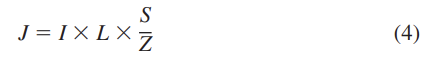
11.2.4 Calculate energy − in./lb (J) to break:
where:
J = energy, in./lb (J),
L = full scale load (FSL), lb (N),
S = crosshead speed, in./min (mm/min),
I = integrator reading (counts), and
Z = integrator (counts/min).