Electrofusion Fittings Solutions from AHP PLASTIK MAKINA
Manufacture of Electro-fusion Fittings Using the AHP Engineering Systems and Production Methods
Production Methods
>EF Fittings=> 1.Socket Fittings 2.Saddle Fittings
>Socket Fittings Production=>
1.(Injection of Insert Part)+(Wire Winding of Insert)+(Injection of the Body of the Fittings)
2.(Winding of Metal Insert)+(Injection of Body of the Fitting)
3.(Injection of the Body of the Fitting)+(Wire Laying)
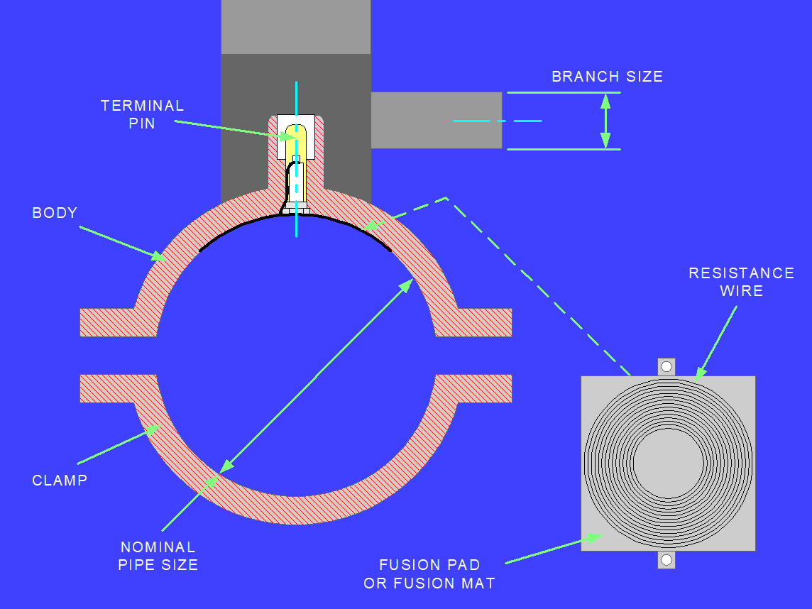
>Saddle Fittings Production=>
1.(Injection of Pad Insert Part)+(Wire Winding of Insert)+(Injection of the Body of the Fittings)
2.(Injection of Pad Insert Part)+(Wire Laying of Insert)+(Injection of the Body of the Fittings)
What is Socket Wire Laying?
>Internal Diameter is Sized
>A helical groove is formed in the internal surface of a moulded fitting or section of pipe(for making PE couplers from PE pipe)
>Resistance wire is laid in the groove
Whole process will be done in one CNC machine
Wire Laying Benefits
Reduced injection moulding <> Increased utilisation of cycle times moulding machines
Moulded fittings are in a stable <> Produces high tolerance condition during wire laying products
Improved welding tolerance <> Increased strength of weld between pipe and fitting
Computer controlled process <> Giving flexibility and reduced setting time
Process reduces capital <> Reduces setting times and set-up costs is easy to operate
Production Overview
Fittings are designed in accordance with:
>ISO Standard 8085-3-2001 (E), EN1555-3:1999 and EN12201
>Fittings are socket and saddle type with resistance wires inserted into contact faces
>Equipment is CNC controlled so the design specifications can be changed during testing
Electrofusion Terminology
Types:
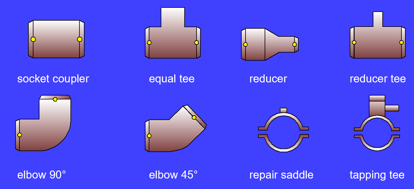
Socket Coupler
Tapping tee
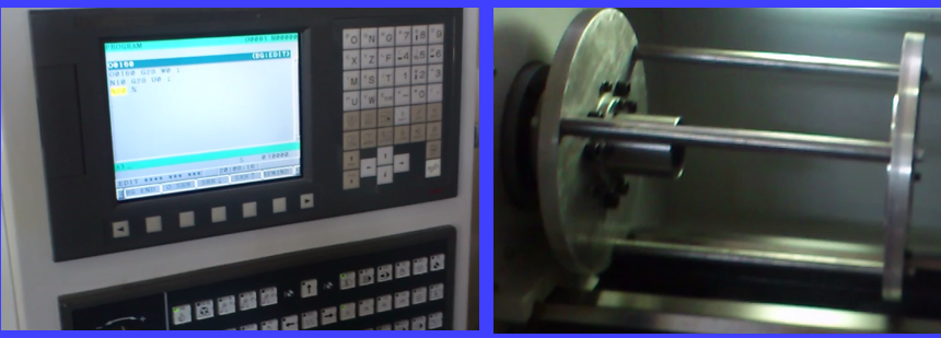
Equipment Description
>Horizontal wire laying machines with FANUC or SIEMENS CNC controllers
>Design layout allows easy access for set-up and component loading using hydraulic grips or pneumatic grips
>3-axis CNC control system enables optimum production cycle times and repeatability
Basic Machine Operation
>Special fixtures located on main spindle of wire laying machine
>Moulded fittings or pipe sections are manually loaded into fixtures and automatically gripped by hydraulic or pneumatic system
>Each fixture is suitable for a range of fittings by only changing end holders of main fixtures
Boring and Wire Laying
In 3 main steps:
> Boring and Chamfering
> Wire Laying Cycle
> Final Boring
Control System
>The CNC system is pre-programmed for the production of each fitting
>Changes can easily be carried out by the operator to incorporate any modifications required in production cycle
>Machines have a memory to store each fitting data
Operating Sequence
>The fitting is manually loaded into the main fixture
>The boring cycle starts at high speed to bore the internal diameter
>The machine is programmed to stop the laying tool at the first termination point
>The wire is manually hooked through the termination hole
>A program is then run which lays wire into the inside surface of the fitting
>The cycle stops when the laying tool reached to the second termination hole
>The wire is manually pulled through the second termination hole
>The boring bar finishes boring to remove any excess material
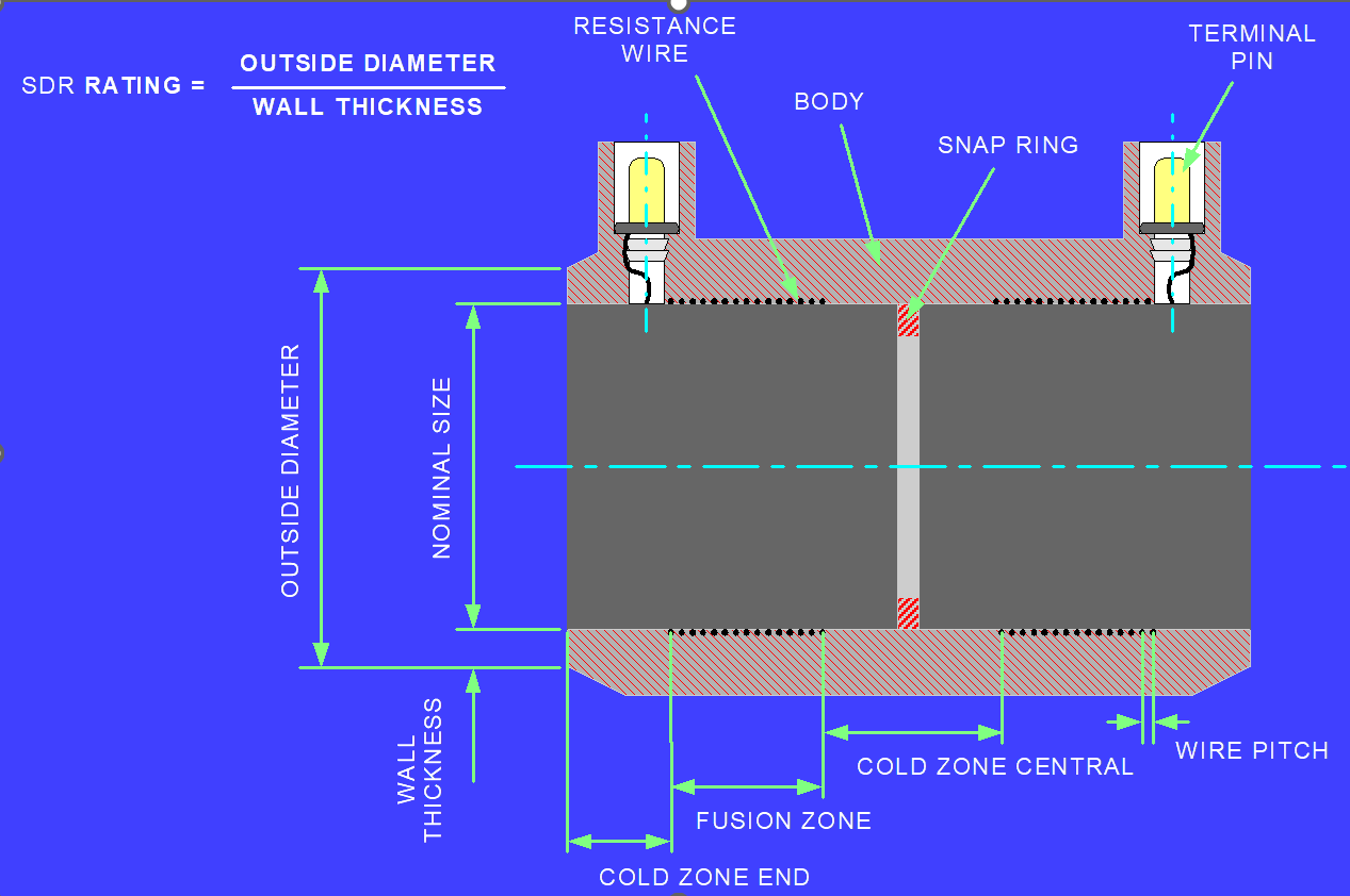
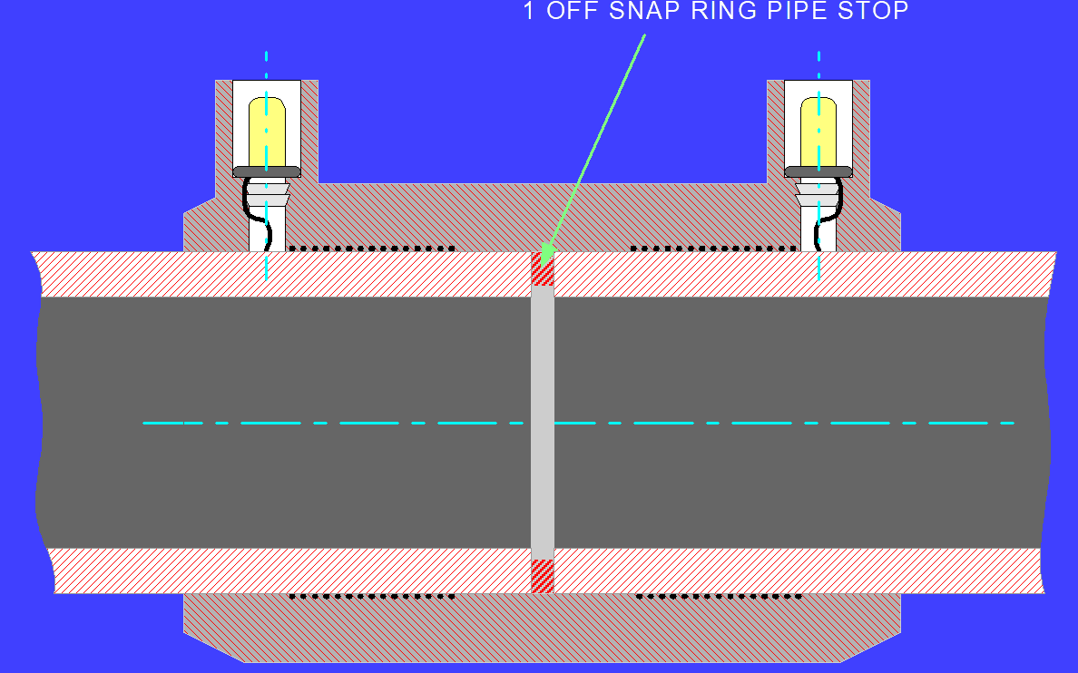
Snap Ring
>The boring bar is doing 3 jobs at the same time: boring+making the slot for stop ring+wire laying
>The snap ring is pushed into the bore of the fitting until it engages with the machined groove
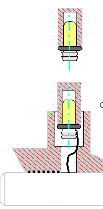
Terminal Pin Mounting
Procedure for Socket Fittings
1.Load terminal pin into press tool
2.Trim wire to length inside terminal housing
3.Place fitting onto mandrel
4.Press terminal pin into fitting
AHP WL200 Horizontal Wire Laying
Typical Fitting Capacity
| sockets / couplers : 25 to 180mm I/D |
| elbows : 25 to 90mm I/D |
| tees (equal) : 25 to 90mm I/D |
| reducers : 25 to 180mm I/D |
Metal Mandrel Process
•Mandrel Winding

•Mandrel put in the mold
•Take out the mandrel to cooling station and taking mandrel out from injected coupler

Technology Consultancy
AHP can offer an electrofusion technology consultancy program
a comprehensive guide to producing electrofusion fittings, and includes CAD design of fittings and relevant components, as well as preliminary electrical data
Package Includes
Component Design
> Fittings design drawings
> drawings of terminal pins, snap rings and other associated items
> initial electrical characteristics, including wire type and size, fusion details and fitting resistance details
> finished drawings of components
>AHP Barcode Creator Software
> software for creating 24-bit barcodes (coding is carried out according to ISO/TR 13950)
>Technical Support
> 12 months technical support by fax or e-mail