
Paraffinic waxes are used for many industrial and consumer applications. We manufacture test and analysis equipment for paraffin wax to determine a wide range of chemical and physical properties. Paraffin was analysis can include purity, contamination, trace components, melting point, oil content and more.
- Melting Point, ASTM D87
- Drop Melting Point ASTM D127
- Oil Content, ASTM D721
- Color, Saybolt Number ASTM D156
- Odor, ASTM D1833
- Penetration, ASTM D1321
- FDA Multi-ring aromatics, FDA 121-1156
- Density, ASTM D1298
- Mechanical Impurities
- Water Content
- Solvent Content, (Benzene, Toluene)
- Water Soluble Acid and Alkali
- Trace analysis
- Contamination analysis
- and additional tests
Here lets see some of these tests in brief.
A- Drop Melting Point ASTM D127
- Apparatus
6.1 Test Tubes—Standard test tubes, 25 mm (1 in.) in outside diameter and 150 mm (6 in.) long. The test tubes shall utilize corks grooved at the sides to permit air circulation and bored in the center to receive the thermometer.
6.2 Bath—A transparent container of not less than 1500-mL capacity, that will permit the immersion of the test tubes to a depth of at least 90 mm and still leave a depth of approximately 15 mm of water below the bottoms of the test tubes.
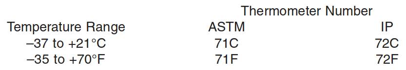
6.3 Thermometer, having a range as shown below and conforming to the requirements as prescribed in Specification E 1 or in specifications for IP Standard Thermometers:
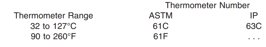
6.4 Bath Thermometer, any suitable type, accurate to 0.5°C (1°F) throughout the required range.
- Procedure
7.1 Secure a sample of sufficient size that is representative of the material under inspection. Use a fresh portion of the sample for each set of two determinations. Melt the sample slowly until the temperature reaches 93°C (200°F), or about 11°C (20°F) above the expected drop melting point, whichever is higher. Place sufficient sample in a flat bottom container to give a sample depth of 12 +- 1 mm. Adjust the temperature of the sample to 6 to 11°C (10 to 20°F) (Note 2) above its drop melting point using any general laboratory thermometer for measurement. Chill one of the test thermometer bulbs to approximately 4°C (40°F). Wipe dry, and, quickly but carefully, immerse the chilled bulb vertically into the heated sample until it touches the bottom of the container (about 12 mm submerged) and withdraw it immediately. Hold the thermometer vertically away from the heat until the surface dulls, and then place it for at least 5 min in water having a temperature of 16 +- 1°C (60 +- 2°F). Prepare another specimen from the same sample using this procedure
NOTE 2—A dipping temperature of 11°C (20°F) above the congealing point in accordance with Test Method D 938 usually will be 6 to 11°C (10 to 20°F) above the actual drop melting point.
7.2 Securely fix the thermometers in the test tubes by means of corks so that the tip of each thermometer is approximately 15 mm above the bottom of its test tube. Insert the test tubes in the water bath which is at 16 +- 1°C (60 6 2°F) and adjust the height of the test tubes so that the immersion marks on the thermometers are level with the top surface of the water. Raise the temperature of the bath at a rate of approximately 2°C (3°F)/min to 38°C (100°F), then at a rate of approximately 1°C (2°F)/min until the first drop of material leaves each thermometer. Record in each case the temperature at which the first drop falls from the thermometer.
B. Penetration Test ASTM D1321
6. Apparatus
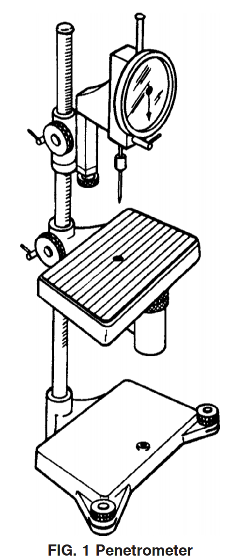
6.1 Penetrometer, for applying the standard needle to the surface of the sample specimen and for measuring the extent of penetration at the conclusion of the test. The penetrometer shall be constructed in such a manner that the accurate placement of the tip of the needle at the level surface of the specimen may be made while maintaining a “zero” reading on the indicator. The apparatus shown in Fig. 1 represents a composite drawing illustrating the two available types of instrument, one with an adjustable table and the other with an adjustable needle assembly; the use of either type of instrument is permissible. The loaded needle must fall, when released, without appreciable friction. The instrument shall be provided with leveling screws and a spirit level to maintain the plunger shaft in a true vertical position. The indicator scale shall be calibrated in tenths of a millimeter division and shall have a range of at least 250 tenths of millimeters.
6.2 Timing Device—An automatic timing release mechanism attached to the penetrometer may be used. Alternatively, a stop watch graduated in 0.1-s intervals may be used.
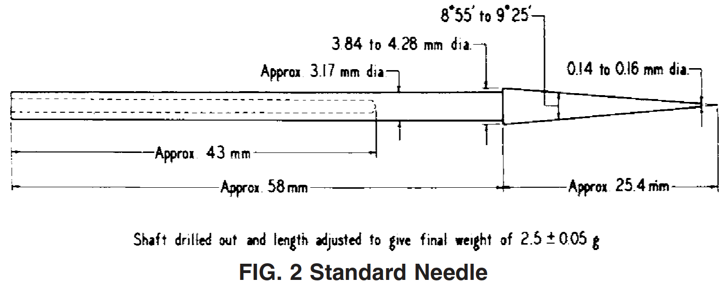
6.3 Needle and Plunger—The needle shall be approximately 83 mm in length and conform to the dimensions shown in Fig. 2. It shall be symmetrically tapered at one end to a cone whose angle shall be within the range from 8°, 55 min to 9°, 25 min over the entire length of the cone. The axis of the cone shall be coincident with the shaft axis within 0.13-mm (0.005-in.) maximum runout (total indicator reading). The tapered section of the needle shall be made from fully hardened and tempered stainless steel, Grade 440-C or equal, Rockwell hardness C57 to 60. After tapering, the point shall be ground off to a truncated cone, the smaller base of which shall be from 0.14 to 0.16 mm in diameter. The truncation shall be square with the needle axis within 2°, and the edge shall be sharp and free from burrs. The conical surface and the truncation shall be finished to a smoothness of 0.2 µm (8 µin.) (rms). The final weight of the needle shall be 2.5 6 0.05 g. The total weight of the plunger shall be 47.5 6 0.05 g; a weight of 50 6 0.05 g is required for mounting on the plunger.
NOTE 2—The National Institute of Standards and Technology will measure and certify the accuracy of penetration needles in accordance with these permissible variations.
6.4 Test Specimen Container, consisting of a brass cylinder open at both ends, having a 25.4 +- 1.6-mm (1 6 1⁄16-in.) inside diameter, 31.8 +- 1.6-mm (11⁄4 +- 1⁄16-in.) height, and 3.2 6
1.6-mm (1⁄8 +- 1⁄16-in.) wall thickness. To prevent slippage of very hard wax, a few screw threads or grooves shall be cut into the center part of the inside wall of the cylinder. The cylinder shall be placed on a base plate of brass, wetted with an equal volume mixture of glycerin and water, when casting a test specimen.
6.5 Test Room or Cabinet, capable of being maintained at
23.9 6 2.2°C (75 6 4°F).
6.6 Water Bath, of at least 10-L capacity, capable of being maintained at the test temperature within 60.1°C (60.2°F) (Note 4). The water bath should be made of glass or other suitable transparent material, or have a window to permit a horizontal view of the specimen. It shall be possible to immerse the test specimen in the bath to a depth of not less than 102 mm (4 in.) and to support it on a perforated conditioning shelf not less than 51 mm (2 in.) from the bottom of the bath. The bath also shall be equipped with a rigid perforated test shelf about 51 mm below the water level to support the specimen during the penetration by the needle.
6.7 Thermometer, for use in the water bath. An ASTM Precision Thermometer, total immersion, having a range from 25 to 55°C or 77 to 131°F and conforming to the requirements for Thermometer 64C or 64F as prescribed in Specification E1 or Thermometer S64C or S64F as prescribed in Specification E2251.
6.8 Brass Plate, 63.5 +- 1.6 mm by 38 +- 1.6 mm by 6.4 +-1.6 mm (21⁄2 +- 1⁄16 in. by 11⁄2 +- 1⁄16 in. by 1⁄4 +- 1⁄16 in.) for supporting test specimen during preparation of the sample. The specimen support is placed on an insulating material, such as corks or rubber stoppers during the cooling period.
7. Preparation of Test Specimen
7.1 Heat the wax sample to at least 17°C (30°F) above its expected congealing point or melting point (as determined by Test Method D938 or Test Method D87, respectively), using care to prevent local overheating. Make sure the sample is
homogeneous and free from air bubbles. In the test room or cabinet maintained at 23.9 +- 2.2°C (75 6 4°F), place the brass plate on a stable support, such as stoppers or corks, and wet the upper surface of the plate with a mixture of equal volumes of glycerin and water. Place the test specimen container on the plate and then pour the melted wax into it in such a way that a convex meniscus is formed. Allow the container and contents to cool in the room at 23.9 +- 2.2°C for 1 h. Then shave any excess wax from the top of the container and remove the brass plate. Place the smooth wax surface up. Condition the specimen in the bath at the test temperature within 0.1°C (0.2°F) for 1 h.
NOTE 3—Very hard waxes occasionally will shrink away from the walls of the test specimen container; in such cases, it is permissible to wedge the specimen in the container.
8. Procedure
8.1 Reverse the penetrometer base and place the penetrometer head over the edge of the water bath and above the perforated test shelf used for supporting the specimen. It may be necessary to place a weight on the base of the penetrometer to counterbalance the head (Note 5). Level the penetrometer and the perforated shelf in the water bath.
NOTE 4—Alternatively, the penetrometer may be placed in the water bath. Likewise, a small bath may be placed on the penetrometer stand provided the test temperature (within 0.1°C (60.2°F)) and the required water circulation above and below the test specimen are maintained and provided further that the temperature of the small bath is measured immediately before testing each specimen using the thermometer specified in 6.7. Emergent stem corrections shall be applied when the correction equals or exceeds 0.05°C (0.1°F). One of the above alternatives will be required if the penetrometer is the adjustable table type.
8.2 Place the specimen container on the perforated test shelf with the smooth wax surface that had contacted the brass plate at the top. Make certain that the container or test shelf cannot teeter during testing. Adjust the water level so that it is at least 25 mm (1 in.) above the top surface of the specimen and maintain it at the test temperature.
NOTE 5—The test may be performed at any temperature in the range from 25 to 55°C (77 to 130°F). Temperatures 25, 35, 45, or 50°C (77, 95, 113, or 122°F) normally are used.
8.3 Place a 50-g weight above the penetrometer needle, making a total load of 100 +- 0.15 g for the needle and all attachments. Observe that the release mechanism does not drag on the shaft and that the indicator on the scale is in the “zero” position. Adjust either the indicator assembly or the table, depending upon the type of instrument, until the tip of the needle nearly touches the surface of the specimen. Securely lock the movable assembly in this position.
8.4 Then, by means of the slow-motion adjustment, bring the needle tip to just touch the surface of the specimen, watching the reflection of the needle tip as an aid to accurate setting. After ensuring the bath temperature is within the proper specifications, release the needle shaft and hold it free for 5.0 +- 0.1 s, timing this interval automatically or with a stop watch graduated to 0.1 s. Then gently depress the indicator shaft until it is stopped by the needle shaft and read the penetration from the indicator scale.
8.5 Make four tests at points about equally spaced (not less than 12.7 mm (1⁄2 in.) apart) on a circumference at least 3.2 mm (1⁄8 in.) from the side of the container. Before each test, wipe the needle carefully toward its point with a clean, dry cloth to remove all adhering wax, position the needle as described in 8.4, and proceed with the test.
C. Oil Content, ASTM D721
5. Apparatus
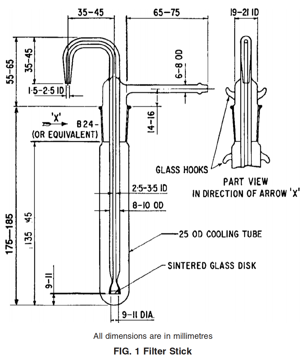
5.1 Filter Stick and Assembly, consisting of a 10-mm diameter sintered glass filter stick of 10 to 15 µm maximum pore diameter as determined by the method in Appendix X1, provided with an air pressure inlet tube and delivery nozzle. It is provided with a ground-glass joint to fit a 25 by 170-mm test tube. The dimensions for a suitable filtration assembly are shown in Fig. 1.
NOTE 2—A metallic filter stick may be employed if desired. A filter stick made of stainless steel and having a 12.7–mm (1⁄2-in.) disk of 10 to 15-µm maximum pore diameter, as determined by Test Method E128, has been found to be satisfactory.5The metallic apparatus is inserted into a 25 by 150–mm test tube and held in place by means of a cork.
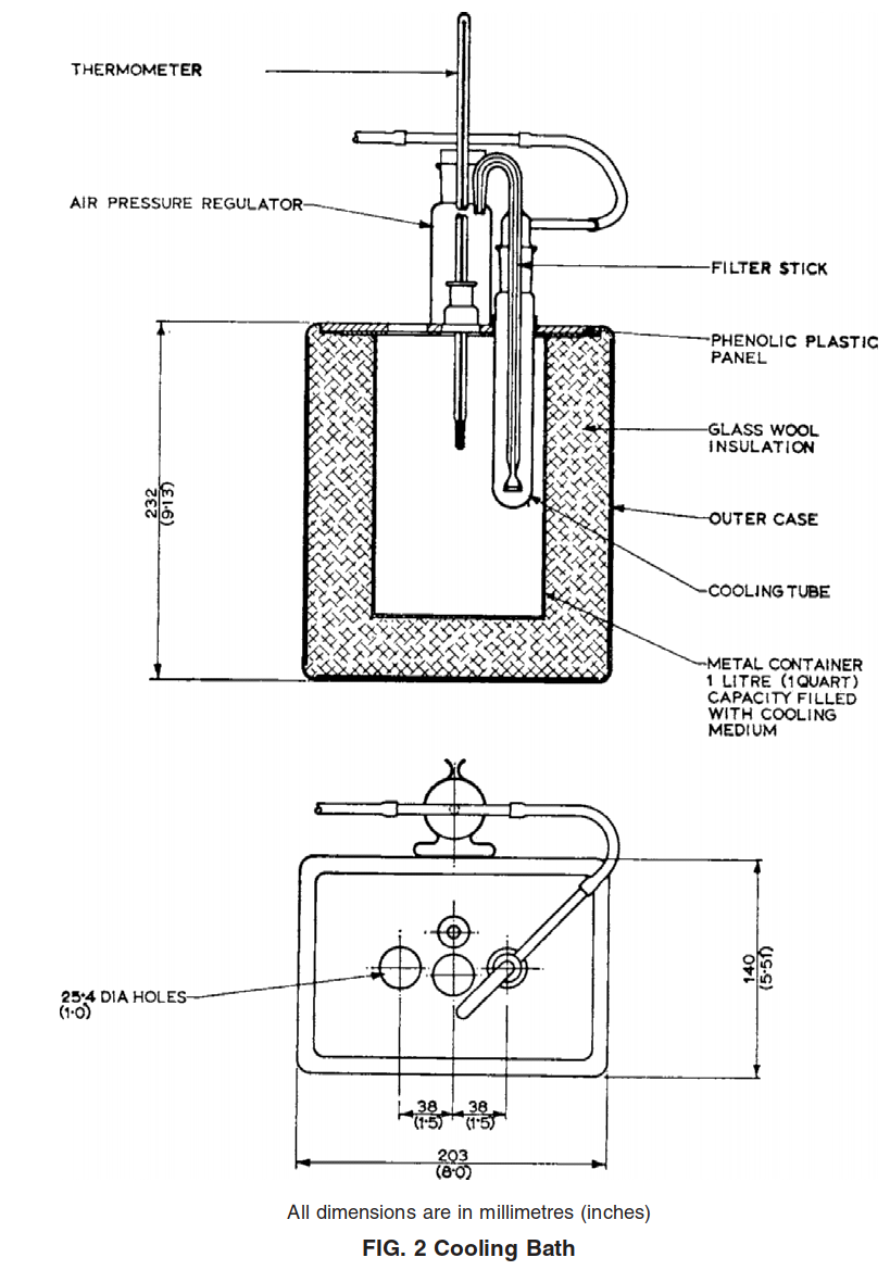
5.2 Cooling Bath, consisting of an insulated box with 30 +- 5-mm (1.2 +- 0.2-in.) holes in the center to accommodate any desired number of test tubes. The bath may be filled with a suitable medium such as kerosine, and may be cooled by circulating a refrigerant through coils, or by using solid carbon dioxide. A suitable cooling bath to accommodate three test tubes is shown in Fig. 2.
5.3 Pipet, or equivalent dispensing device capable of delivering 1 +- 0.05 g of molten wax.
5.4 Transfer Pipet, or equivalent volume dispensing device, capable of delivering 15 +- 0.06 mL.
5.5 Air Pressure Regulator, designed to supply air to the filtration assembly (8.5) at the volume and pressure required to give an even flow of filtrate. Either the conventional pressure-reducing valve or a mercury bubbler-type regulator has been found satisfactory. The latter type, illustrated in Fig. 3, consists of a 250-mL glass cylinder and a T-tube held in the cylinder by means of a rubber stopper grooved at the sides to permit the escape of excess air. The volume and pressure of the air supplied to the filtration assembly is regulated by the depth to which the T-tube is immersed in mercury at the bottom of the cylinder. Absorbent cotton placed in the space above the mercury prevents the loss of mercury by spattering. The air pressure regulatory is connected to the filter stick and assembly by means of rubber tubing.

5.6 Temperature Measuring Device:
5.6.1 Thermometer, having a range as shown below and conforming to the requirements as prescribed in Specification E1, or in the Specification for IP Standard Thermometers.
5.6.2 Temperature measuring devices other than those described in 5.6.1 are satisfactory for this test method, provided that they exhibit the same temperature response as the equivalent mercury-in-glass thermometers.
5.7 Weighing Bottles, glass-stoppered, having a typical capacity of 15 to 25 mL.
5.8 Evaporation Assembly, consisting of an evaporating cabinet and connections, essentially as illustrated in Fig. 4, and capable of maintaining a temperature of 35 +- 1°C (95 +- 2°F) around the evaporation flask. Construct the jets with an inside diameter of 4 +- 0.2 mm for delivering a stream of clean, dry air vertically downward into the weighing bottle. Support each jet so that the tip is 15 +- 5 mm above the surface of the liquid at the start of the evaporation. Supply purified air at the rate of 2 to 3 L/min per jet. One way to purify the air is by passage through a tube of approximately 10-mm bore packed loosely to a height of approximately 200 mm with absorbent cotton. Periodically check the cleanliness of the air by evaporating 4 mL of methyl ethyl ketone by the procedure specified in 8.5. When the residue does not exceed 0.1 mg, the evaporation equipment is operating satisfactorily.

5.9 Analytical Balance, capable of reproducing weights to 0.1 mg.
5.10 Wire Stirrer—A piece of stiff wire, made of iron, stainless steel, or Nichrome wire of about No. 20 B & S (0.9 mm in diameter) or 16 swg gage, 250 mm long. A 10-mm diameter loop is formed at each end, and the loop at the bottom end is bent so that the plane of the loop is perpendicular to the wire.
6. Reagents
6.1 Methyl Ethyl Ketone, conforming to the specifications of the Committee on Analytical Reagents of the American Chemical Society.
6.2 Store the solvent over anhydrous calcium sulfate (5 weight % of the solvent). Filter prior to use.
6.3 Air Supply, clean and filtered.
7. Sample
7.1 If the sample of wax is 1 kg (2 lb) or less, obtain a representative portion by melting the entire sample and stirring thoroughly. For samples over 1 kg (2 lb), exercise special care to ensure obtaining a truly representative portion, bearing in mind that the oil may not be distributed uniformly throughout the sample, and that mechanical operations may express some of the oil.
8. Procedure
8.1 Melt a representative portion of the sample, using a water bath or oven maintained at 70 to 100°C (158 to 212°F). As soon as the wax is completely melted, thoroughly mix. Preheat the pipet or equivalent measuring device in order to prevent the solidification of wax in the tip, and withdraw a portion of the sample as soon as possible after the wax has melted. The mass of wax transferred to the test tube must be 1.00 +- 0.05 g. Allow the test tube to cool, and weigh to at least the nearest 1 mg.
NOTE 4—The weight of a test tube which is cleaned by means of solvents will not vary to a significant extent. Therefore, a tare weight may be obtained and used repeatedly.
8.2 Pipet 15 mL of methyl ethyl ketone into the test tube and place the latter just up to the level of its contents in a hot water
or steam bath. Heat the solvent wax mixture, stirring up and down with the wire stirrer, until a homogeneous solution is obtained. Exercise care to avoid loss of solvent by prolonged boiling.
NOTE 5—Very high-melting wax samples may not form clear solutions. Stir until the undissolved material is well dispersed as a fine cloud.
8.2.1 Plunge the test tube into an 800-mL beaker of ice water and continue to stir until the contents are cold. Remove the stirrer. Remove the test tube from the ice bath, wipe dry on the outside with a cloth, and weigh to at least the nearest 0.1 g.
NOTE 6—During this operation the loss of solvent through vaporizations should be less than 1%. The weight of the solvent is therefore practically a constant, and after a few samples are weighed, this weight, approximately 11.9 g, can be used as a constant factor.
8.3 Insert the temperature measuring device into the test tube and place the test tube containing the wax-solvent slurry in the cooling bath, which is maintained at –34.5 +- 1.0°C (–30.0 +- 2.0°F). During this chilling operation it is important that stirring by means of the temperature measuring device be almost continuous, in order to maintain a slurry of uniform consistency as the wax precipitates. Do not allow the wax to set up of the walls of cooling vessel nor permit any lumps of wax crystals to form. Continue stirring until the temperature reaches –31.7 +- 0.3°C (–25.0 +- 0.5°F).
8.4 Remove the temperature measuring device from the tube and allow it to drain momentarily into the tube; then immediately immerse in the mixture the clean dry filter stick which has previously been cooled by placing it in a test tube and holding at –34.5 +- 1.0°C (–30.0 +- 2.0°F) in the cooling bath for a minimum of 10 min. Seat the ground-glass joint of the filter so as to make an airtight seal. Place an unstoppered weighing bottle, previously weighed together with the glass stopper to the nearest 0.1 mg, under the delivery nozzle of the filtration assembly.
NOTE 7—Take every precaution to ensure the accuracy of the weight of the stoppered weighing bottle. Prior to determining this weight, rinse the clean, dry weighing bottle and stopper with methyl ethyl ketone, wipe dry on the outside with a cloth, and place in the evaporation assembly to dry for about 5 min. Then remove the weighing bottle and stopper, place near the balance, and allow to stand for 10 min prior to weighing. Stopper the bottle during this cooling period. Once the weighing bottle and stopper have been dried in the evaporation assembly, lift only with forceps. Take care to remove and replace the glass stopper with a light touch.
8.5 Apply air pressure to the filtration assembly, and immediately collect about 4 mL of filtrate in the weighing bottle. Release the air pressure to permit the liquid to drain back slowly from the delivery nozzle. Remove the weighing bottle immediately, and stopper and weigh to at least the nearest 10 mg without waiting for it to come to room temperature. Unstopper the weighing bottle and place it under one of the jets in the evaporation assembly maintained at 35 +- 1°C (95 +- 2°F), with the air jet centered inside the neck, and the tip 15 +- 5 mm above the surface of the liquid. After the solvent has evaporated, which usually takes less than 30 min, remove the bottle and stopper, and place them near the balance. Allow to stand for 10 min and weigh to the nearest 0.1 mg. Repeat the evaporation procedure, using a 5-min evaporation period instead of 30 min, until the loss between successive weightings is not over 0.2 mg.