
4 Principle
A test specimen having a specified precut slit is subjected to a tearing force generated by the energy stored in a pendulum of specified dimensions. The energy expended in tearing the specimen is used to calculate the tear resistance of the specimen.
5 Apparatus
The test machine shall be of the Elmendorf type {an example of a suitable test machine is shown diagrammatically in figure I), comprising the following.
5.1 Stationary jaw, accurately aligned with a movable jaw carried on a pendulum, preferably formed by a sector of a circle, free to swing on ball bearings or other substantially frictionless bearings. Each jaw shall have a clamping surface of not less than 25 mm in the horizontal direction [dimension b (see
figure 1) 1 and not less than 15 mm in the vertical direction (dimension C). The thickness of the fixed portion of each jaw shall be between 9 and 13 mm (dimension a). When the pendulum is in the initial position, ready for the test, the jaws shall be separated by a distance of 2,8 ± 0,3 mm and so aligned that the test specimen clamped in them lies in a plane perpendicular to the plane of oscillation of the pendulum, with the edges of the jaws gripping the test specimen in a horizontal line, a perpendicular to which through the axis of suspension of the pendulum (i.e. the distance between the axis and the top edges of the clamping jaws) is 104 ± 2 mm long and makes an angle of 27,5° I 30′ with the plane of the test specimen.
5.2 Means for holding the pendulum in a raised position and for releasing it without imparting shock.
5.3 Means for determining the energy expended by the pendulum in tearing a specimen. This usually consists of a circumferential scale on the pendulum which indicates against a pointer. The machine shall be accurately calibrated (allowing for friction and windage losses) to enable the scale reading to be used to give the force required to tear the standard test specimen in newtons, with an accuracy to within 1 % . This calibration shall be periodically checked. Annexes A and B give instructions for the adjustment and calibration of the apparatus.
5.4 Incremental masses, to add to the pendulum to increase the tearing force capacity of the machine.
5.5 Suitable measuring equipment, to measure the thickness of the material being tested by the methods Defied in ISO 4591 and ISO 4593.
6 Test specimens
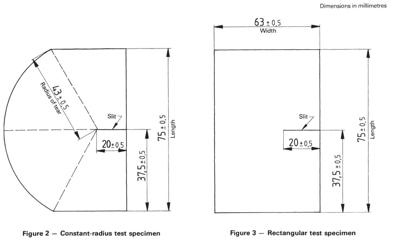
6.1 The test specimen shall have the shape and dimensions shown in figures 2 or 3. The preferred or referee specimen shall be the constant-radius specimen (figure 2) because of better reproducibility (see 8.5).
6.2 The test specimen may be cut from the sample using templates and a sharp knife. Special attention shall be given to the cutting of the 20 + 0,5 mm slit, which shall be free of nicks and ragged edges.
NOTE — Some testing machines have a permanent and integral knife by which the slit can be cut into the test specimen after mounting in the jaws of the machine. In such cases, the sharpness of this knife and its ability to cut the slit to the correct dimensions should be frequently checked.
6.3 Unless otherwise specified by the specification for the material being tested, five test specimens lor five groups of test specimens (see the note)1 shall be tested in each principal direction of the film sample, cut from positions evenly spaced across the width of the sample.
NOTE — In the case of films of low tear strength, it is permissible to test a group of two or more test specimens simultaneously in order to meet the requirements of 8.3. Cut the individual test pieces for each group adjacent to each other, but space the groups approximate evenly across the width of the sample. However, certain specimens in the same sandwich may tear obliquely in opposite directions, which may lead to falsely high results. When this testing behaviors is encountered, single specimens must be tested even though scale readings may be in the range below 20. For thin film, it is recommended that single specimens and a lower capacity tester be used rather than several specimens and a higher capacity machine.
6.4 When testing film in the machine (longitudinal) direction, test specimens shall be oriented so that their width is cut in the longitudinal direction and, similarly, specimens for transverse tear strength determinations shall be cut with their width in the transverse direction.
8 Procedure
8.1 Determine the thickness of the material being tested by the method specified in ISO 4591 and ISO 4593.
NOTE – ISO 4593 is not suitable for use with embossed film and sheeting.
8.2 Check that the Elmendorf apparatus is level. Lift and arrest the pendulum, set the indicating mechanism to the starting position and gently release the pendulum. Check that the pointer indicates zero and adjust if necessary according to the manufacturer’s instructions.
8.3 Carry out a few tests by the procedure specified in 8.4 to
check whether augmenting weights are required or a number of test specimens need to be tested simultaneously (see the note to 6.3) so that on any test the energy of the pendulum absorbed in tearing lies between 20 and 80 % of the total energy of the pendulum. Check the zero setting and adjust according to the manufacturer’s instructions each time that augmenting weights are fitted or removed.
8.4 Lift and arrest the pendulum of the machine and set the indicating mechanism to its starting point. Carefully position the test specimen, or group of test specimens, in the jaws of the grips so that the slit is centrally disposed between the fixed and movable jaws of the machine and tighten the clamps firmly (see the note). Carefully release the pendulum and read from the scale the force expended in tearing the specimen or group of test specimens.
NOTE — When the machine is fitted with an integral slitting knife, clamp the specimen as in 8.4 and then operate the knife to produce the slit (see the note to 6.2).
8.5 When constant-radius test specimens (see figure 2) are used, reject any tests in which the line or tear deviates outside the constant radius section and test additional specimens to replace those rejected.
When rectangular test specimens (see figure 3) are used, reject any tests in which the line of tear deviates more than 10 mm from the line of the slit, except when the tear is following a specific line of an embossed pattern, and test additional specimens to replace those rejected. When the tear deviation consistently exceeds 10 mm, use the constant-radius test specimens.
9 Calculation and expression of results
9.1 From the scale readings, determine, according to the machine manufacturer’s instructions, the force in newtons required to tear each test specimen, taking account of any use of augmenting weights and groups of specimens torn simultaneously. Record this force in newtons as the tear resistance of each test specimen.
9.2 Calculate the arithmetic mean tear resistance in each principal direction of the film or sheeting.
9.3 If required, calculate the standard deviation for each set of results.

Annex A
Adjustment and maintenance of the instruments
Follow the procedure described below for each of the pendulum/additional weight combinations used.
A.1 Inspection
Check the following items and make any necessary adjustments.
a) Check that the pendulum shaft is not bent.
b) Check that the distance between clamps is 2,8 + 0,3 mm and that when the pendulum is in its initial position, the clamps are in alignment.
c) Check that the knife fitting is secure, and that the cutting edge is sharp and undamaged. The blade shall be situated midway between, and at right angles to, the top of the clamps.
d) Ensure that the pointer is undamaged and rigidly attached to the sleeve.
A.2 Levelling
Mount the instrument on a rigid bench and, if possible, firmly attach it to the bench.
With the pendulum clamp closed, adjust the level of the instrument so that the pendulum hangs vertically and the index marks on the pendulum and base coincide. With the stop depressed, displace the pendulum slightly and after it comes to rest, check that the index marks still coincide.
A.3 Zero adjustment
After Ieveling, operate the instrument several times with clamps empty and closed to ascertain whether the pointer registers zero. If zero is not registered, move the adjustable pointer stop.
A.4 Pendulum friction
Make a reference mark on the stop mechanism 25 mm to the right of the edge of the pendulum catch. Raise the sector to its initial position and set the pointer so that it does not meet the pointer stop when the instrument is operated.
When the sector is released and the pendulum stop held down, the sector should make at least 35 complete oscillations before the edge of the sector which engages with the catch no longer passes to the left of the reference mark. Otherwise, clean, oil or adjust the bearing.
A.5 Tearing length
Adjust the position of the knife. Check that the tearing length is 43,0 + 0,5 mm. If this is not so, adjust the dimensions of the guillotme or template used.
Annex B
Calibration of the instrument
Calibration of the instrument may be checked by measuring the work done by the pendulum in raising various attached weights. The indicated scale reading is then compared with the amount of work done. Many tear testers are provided with a threaded hole to aid the attachment of weights.
The position of the centre of gravity of the attached weights should be known.
Set up the instrument and check it as specified in annex A. With various weights attached, operate the instrument without a test piece in position and determine the scale reading and height above a horizontal datum surface of the centre of gravity of the additional weight corresponding to this scale reading.
Calculate the correct scale readings Y from the formula
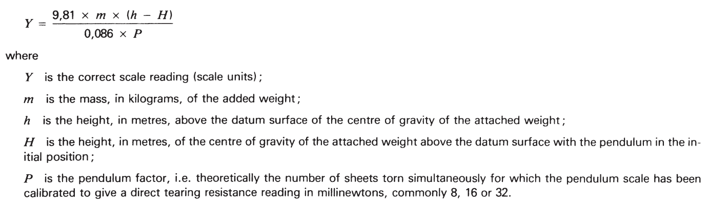
For routine calibration checks, an alternative procedure is to prepare a graph giving (h — H) for different scale readings. It is then only necessary to determine the scale reading for a given added weight, to read off the corresponding value of (h — H) and to calculate the error using this value.
Calculated and indicated scale readings should agree to within ± 1 % . if they do not, the fault should, if possible, be found and remedied. Otherwise, prepare a correction chart and adjust the results accordingly.
Trust the AHP Tear Tester to measure Elmendorf Tear Strength of a variety of materials. This method developed over a century ago established the industry standards used worldwide today to measure tear strength.
It provides a rapid and precise way to evaluate the tear resistance of sheet materials including paper, textiles, roofing products, plastic film, and foils.
The electronic model features a touch-screen panel that allows for a simple one-touch process to run tear tests and track data. Two different pendulums are available with various augmenting weights and can be configured to meet capacities from 200g-12,800g. Capacity will be chosen as per final application of machine for different sectors.
**Test results should fall between 20% and 80% of your pendulum capacity. For example, if you are using a 1600 gram pendulum, you should expect to get tear results between 1280 grams and 320 grams**
- Touch-screen menu
- Easy-mount pendulums and augmenting weights (Per customer request)
- Configurable display for results and reporting
- Sample size 63*75mm
- Slit length 20mm
- Thermal printer included
- Export of test results data MS EXCEL
- USB Port connections for data export
- One-touch pneumatic clamping and pendulum release