
F.1 Principle
The test specimen is subjected to a specified number of cyclic operations whilst under lateral and longitudinal tension.
F.2 Apparatus
F.2.1 Vertically operated testing machine of the type shown in Figure F.1 and providing the following facilities. a) Means of holding the test specimen firmly at the bottom end, with the fastener in the closed position, without the chain being damaged.
b) Means of separately gripping the two stringers at the other end so that the fastener beyond the slider is open. These gripping devices form the means of applying longitudinal spring balance forces to the fastener and are therefore connected together by a swivel-plate or other similar device, so that the fastener can be centralized when the forces are applied. The gripping devices also swivel at the points of connection to the swivel-plate to facilitate the operation of the slider on the test specimen. The distance between the gripping devices is such that when the slider is at the lowest point in the cycle the two ends of the fastener subtend an angle of approximately 60° (see Figure F.1).
c) Means of gripping the tapes securely midway along the traversed length at opposite points of the testing zone so that the clamps can be subjected to force by means of spring balances. The clamps are mounted so that they are “floating”, i.e. free to follow the natural direction of opening of the test specimen. The clamps are capable of moving 5 mm in the direction of the pulleys, and setting pads are provided to hold the clamps in position until they are secured to the tapes. The spring balances are of the tubular type and are 100 N balances for the lateral tension and 50 N balances for the longitudinal force. In each case the scale is 44 mm in length. The 100 N balance has a spring rating of 2.25 N/mm and the 50 N balance one of 1.10 N/mm. They are graduated in 1 N steps and accurate to within 5 N on each reading.
d) Means of applying a regular reciprocating action, through the medium of the puller, to the slider on the test specimen. The clamp or other gripping device may provide an indirect form of connection in which the clamp is in two parts, one of which is attached to the reciprocating device and the other to the puller on the specimen. This method of attachment can incorporate a spring mechanism or other feature to withdraw any automatic locking device fitted to the slider on the specimen.

F.3 Procedure
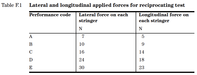
F.3.1 Mount the test specimen in the vertical plane so that the bottom stop is away from the spring balance end of the testing machine. Leave the stringers separate at the other end so that they can be individually mounted in the testing machine (see Figure F.1). The lateral and longitudinal forces applied are as given in Table F.1.
F.3.2 Arrange the machine so that the length of traverse of the slider is from 75 mm to 90 mm in each direction, a to-and-fro movement of 150 mm to 180 mm forming a cycle. The procedure then follows the steps indicated below.
Operate the testing machine by hand until the slider gripper is in the lowest position, and place in position the setting pads. Clamp the puller, ensuring that any locking device is withdrawn.
Place the fastener loosely in position in the top tape clamp, A.
Secure the fastener ends in the bottom tape clamps, B.
Take hold of the fastener C at the upper end and draw upwards until pin D prevents any further upward movement, without stretching the tape. Tighten clamp A. If the fastener is completely closed, then the tape ends that are attached by the bottom tape clamps are too long. To overcome this, release clamps B, F and A and cut off a length of each bottom tape end. To re-assemble start at Step 3.
Apply the appropriate longitudinal forces given in Table F.1 by adjusting the spring balances E.
Secure side clamps F to the fastener tapes, leaving gaps of 5 mm between the side clamps and the chain at their nearest points. Ensure that the centre-lines of the clamps coincide with the strings that pass over the pulleys. Ensure that the clamps, F, are held firmly against the setting pads, J, whilst securing the clamps to the fastener tape. Withdraw the setting pads after fixing the clamps.
Apply the appropriate lateral forces given in Table F.1 by adjusting spring balances G.
Set the counter to zero. Set machine in motion for one cycle only to the equalize position of test specimen. Check the forces of spring balances E and G and adjust when necessary. When the slider is in the lowest position set the adjusting screws, H, 5 mm away from the side clamps, F.
Set the machine in motion at a constant speed of 30 cycles per minute. Once the test has started, do not readjust the spring balances E and G. Leave the machine in operation until the specified number of cycles is completed or failure occurs.
- According to BS 3084
- Spring balances of 100N and 50N
- Speed of 30 cycles/minute
- Digital cycle indicator